Exposure device and device manufacturing method

A technology of exposure device and optical element, which is applied in semiconductor/solid-state device manufacturing, photolithographic process exposure device, microlithography exposure equipment, etc., can solve equipment malfunction, deterioration of exposure accuracy of exposure device, and measurement accuracy of measuring instrument Deterioration and other problems, and the effect of preventing deterioration of exposure accuracy, malfunction, and deterioration of exposure accuracy and measurement accuracy can be achieved.

Inactive Publication Date: 2007-11-07
NIKON CORP
View PDF26 Cites 6 Cited by
  • Summary
  • Abstract
  • Description
  • Claims
  • Application Information

AI Technical Summary

Problems solved by technology

When the liquid flows out or scatteres, for example, the liquid that has flowed out may adhere to the equipment constituting the exposure device, causing the equipment to malfunction or be damaged.
In addition, when the device is, for example, a measuring instrument for optically measuring the position of the substrate, the measurement accuracy of the measuring instrument may deteriorate due to the influence of the outflowing liquid.
Once the equipment malfunctions or the measurement accuracy deteriorates, the exposure accuracy of the exposure device will also deteriorate.

Method used


Image

  • Exposure device and device manufacturing method
  • Exposure device and device manufacturing method
  • Exposure device and device manufacturing method

Examples


no. 1 approach

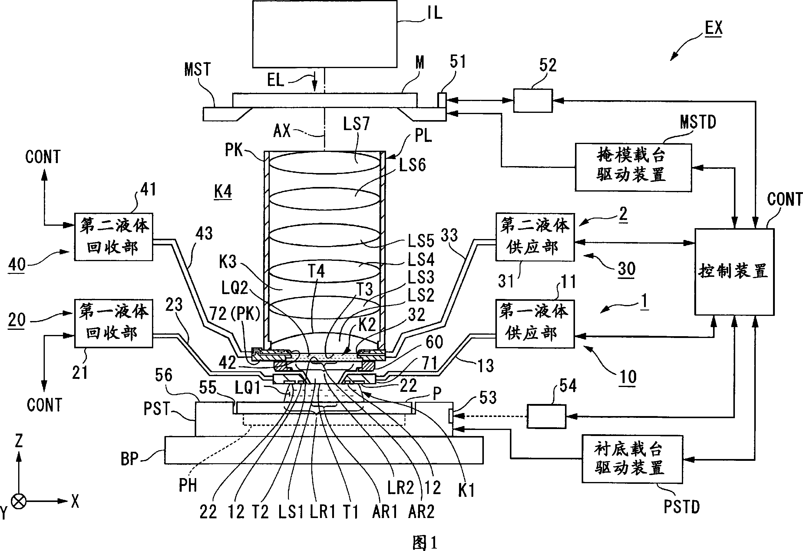
[0067] FIG. 1 is a schematic configuration diagram showing an exposure apparatus EX according to a first embodiment. In FIG. 1 , the exposure apparatus EX includes: a movable mask stage MST that holds a mask M; a substrate stage PST that includes a substrate holder PH that holds a substrate P; and a mask to be held by the mask stage MST. Illumination optical system IL for illuminating M with exposure light EL; projection optical system PL for projecting and exposing a pattern image of mask M illuminated by exposure light EL onto substrate P held by substrate stage PST; collectively controlling exposure A control device CONT for the overall operation of the device EX.

[0068] The exposure apparatus main body EX of the present embodiment is a liquid immersion exposure apparatus to which a liquid immersion method is applied in order to substantially shorten the exposure wavelength to improve the resolution, and to substantially increase the depth of focus. The first liquid imme...

no. 2 approach

[0144] Next, as a second embodiment, the procedure for replacing the first optical element LS1 will be described.

[0145] In the first liquid LQ1 of the first liquid immersion region LR1 (the first space K1), foreign matters caused by, for example, a photosensitive agent (photoresist), impurities etc. generated from the substrate P, etc. are mixed, so there is This first liquid LQ1 may be contaminated. Since the first liquid LQ1 in the first liquid immersion region LR1 is also in contact with the bottom surface T1 of the first optical element LS1 , the contaminated first liquid LQ1 may contaminate the bottom surface T1 of the first optical element LS1 . In addition, impurities suspended in the air may also adhere to the bottom surface T1 of the first optical element LS1 exposed on the image plane side of the projection optical system PL. Therefore, the contaminated first optical element LS1 is replaced at the prescribed time.

[0146] Before replacing the first optical elem...

no. 3 approach

[0155] Next, a third embodiment will be described with reference to FIG. 18 . A characteristic part of this embodiment is that the second nozzle member 72 vacuum-adsorbs and holds the first optical element LS1 . In FIG. 18 , the second nozzle member 72 includes a holding portion 100 for holding the first optical element LS1 by vacuum suction. The holding portion 100 is provided on the bottom surface 72K of the second nozzle member 72 opposite to the top surface T2 of the first optical element LS1 . The bottom surface 72K of the second nozzle member 72 faces a region different from the region through which the exposure light EL passes of the top surface T2 of the first optical element LS1. The holding portion 100 includes a vacuum suction groove 101 annularly formed on the bottom surface 72K of the second nozzle member 72 . In a part of the vacuum suction tank 101, suction holes connected to a vacuum system not shown are formed. By driving the vacuum system with the bottom s...


PUM


Abstract

The invention provides an exposure device which applies an exposure light to a substrate (P) via a projection optical system (PL) so as to expose the substrate (P). The projection optical system (PL) includes a first optical element (LS1) nearest to the image plane of the projection optical system (PL) and a second optical element (LS2) arranged near to the image plane next to the first optical element (LS1). The exposure device further includes a second collection opening (42) arranged at a position higher than a lower surface (T3) of the second optical element (LS2) for collecting second liquid (LQ2) contained in a second space (K2) between an upper surface (T2) of the first optical element (LS1) and the lower surface (T3) of the second optical element (LS2).

Description

technical field [0001] The invention relates to an exposure device and a device manufacturing method for exposing a substrate. [0002] This application claims priority based on Japanese Patent Application No. 2004-349730 filed on December 2, 2004 and Japanese Patent Application No. 2005-173339 filed on June 14, 2005, the contents of which are incorporated herein. Background technique [0003] In photolithography, which is one of the manufacturing steps of microdevices such as semiconductor devices and liquid crystal display devices, an exposure apparatus for exposing a pattern formed on a mask onto a photosensitive substrate is used. This exposure apparatus has a mask stage for holding a mask and a substrate stage for holding a substrate, and projects the pattern of the mask onto the substrate through a projection optical system while moving the mask stage and the substrate stage sequentially. . In the manufacture of micro devices, miniaturization of patterns formed on su...

Claims


Application Information

Patent Timeline
Patent Type & Authority Applications(China)
IPC IPC(8): H01L21/027G03F7/20
Inventor 冈田尚也菅原龙
Owner NIKON CORP
Why Eureka
Try Eureka