Exposure device

A technology of exposure device and exposure stage, which is applied to exposure devices in photo-engraving process, exposure equipment for microlithography, optics, etc. The effect of shortening, less elongation or deformation

Inactive Publication Date: 2008-05-07
ADTEC ENG
View PDF2 Cites 2 Cited by
  • Summary
  • Abstract
  • Description
  • Claims
  • Application Information

AI Technical Summary

Problems solved by technology

[0008] However, in the case of using the method of opening the space between the film mask and the mask holder to the atmosphere in Patent Document 1, there is a problem that sufficient adhesion of the film mask cannot be obtained due to insufficient pressure.
Moreover, only constant pressure such as atmospheric pressure can be used, and there is a problem that it is difficult to obtain the best adhesion according to various conditions by changing the pressure.
[0009] On the other hand, in the case of adopting the configuration of Patent Document 2 in which the back side of the film mask is pressurized in advance before vacuum sealing, there is a problem that the process of bonding the film will take longer because the pressurization takes time.
In addition, there are also problems such as the possibility of deformation such as elongation of the film mask

Method used


Image

  • Exposure device
  • Exposure device
  • Exposure device

Examples


Embodiment Construction

[0025] Embodiments of the exposure apparatus for manufacturing a printed wiring board according to the present invention will be described below with reference to the drawings.

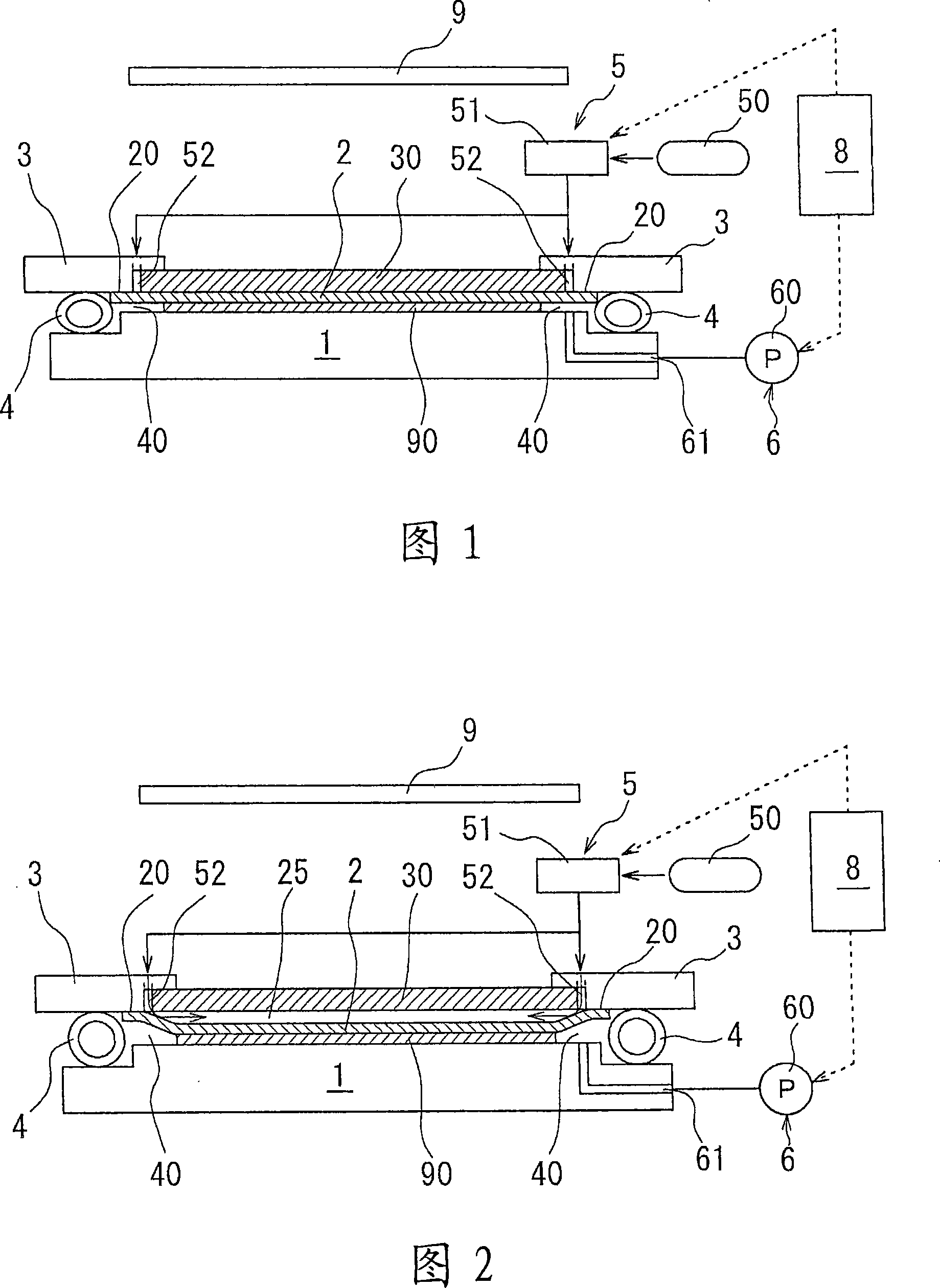
[0026] In FIG. 1 , a substrate 90 for printed wiring to which a photoresist is applied is placed on an exposure table 1 . The exposure stage 1 can move in the XY direction and can move up and down. It can also be turned in the horizontal direction. Explanations on these moving, elevating and rotating mechanisms are omitted.

[0027] The film mask 2 on which the circuit pattern is drawn is placed facing the substrate 90 , and the film mask 2 is brought into close contact with the substrate 90 , and the circuit pattern is burned on the substrate 90 by exposure from the light source 9 .

[0028] In addition, although the exposure table 1 and the substrate 90 are arranged in the vertical direction in FIG. 1 , it is not limited to this, and may be arranged in reverse, or may be arranged vertically with t...


PUM


Abstract

The invention provides an exposure device which is high in accuracy and can have the exposure time shortened. A lighthouse (1) is elevated so as to contact a film mask (2) to a substrate (90) and then to form an enclosed place (40). A pressure reducing pump (60) is used for reducing the pressure. A one-time enclosure between the film mask (2) and the substrate (90) is conducted. Then, a pressurized air with a pressure ranging from 1kPa to 20kPa is led in from a guide hole (52), thus forming a pressuring space (25) between the film mask (2) and a piece of glass (30). The film mask (2) and the substrate (90) are further sealed, thus completing a second enclosure. As the first enclosure has made the film mask (2) and the substrate (90) sealed, a small amount of air in the guide hole (52) can be led in, and also a small amount of air is blown out under the inflation during the pressurizing. So the inside guide of the air can be fulfilled in a short period of time, without such defect as the deformation due to the inflation of the film mask (2).

Description

technical field [0001] The present invention relates to an exposure device used for a printed wiring board. Background technique [0002] In recent years, printed wiring boards are manufactured using exposure equipment, and photolithography (photolithography) is used as a manufacturing method. A predetermined pattern is sensitized and then etched to form a pattern on the substrate. [0003] In this exposure apparatus, generally, a resin film mask is mainly used as an original plate on which a pattern original is drawn, and the film mask is held on a glass mask holder for use. And in order to improve the adhesiveness between this film mask and a board|substrate, the so-called vacuum sealing method which draws a vacuum between them and makes them adhere|attach is often used. [0004] This vacuum sealing method is effective when the substrate surface is flat, but if the substrate surface has unevenness or undulations, the mask may not follow the substrate, resulting in poor m...

Claims


Application Information

Patent Timeline
Patent Type & Authority Applications(China)
IPC IPC(8): G03F7/20H01L21/027
CPCG03F7/7035
Inventor 五十岚晃今井洋之川俣晴男杉田健一江部克己田口阳介
Owner ADTEC ENG
Why Eureka
Try Eureka