Counter-flow type return-flow condensation pipe

A reflux condensing tube and counter-flow technology, applied in the field of counter-current reflux condensing tubes, can solve the problems of small application range, difficult reflux operation, high volatilization loss, etc., and achieve the effects of good cooling effect, high heat conduction efficiency and wide application range.

Inactive Publication Date: 2007-11-14
JINHUA VOCATIONAL TECH COLLEGE
View PDF0 Cites 8 Cited by
  • Summary
  • Abstract
  • Description
  • Claims
  • Application Information

AI Technical Summary

Problems solved by technology

Therefore, in the reflux operation of some fluids with a boiling point higher than 140°C, the air condenser can only be used as the coolant, but because the heat transfer efficiency of air is much lower than that of water, the air condenser The cooling effect is very poor, the cooled fluid will have more volatilization loss, and it is difficult to perform satisfactory reflux operation
Since the existing reflux condenser is limited by the boiling point temperature range of the cooled fluid, its application range is small

Method used


Image

  • Counter-flow type return-flow condensation pipe

Examples


Embodiment Construction

[0010] The present invention will be further described below with reference to the accompanying drawings and examples.

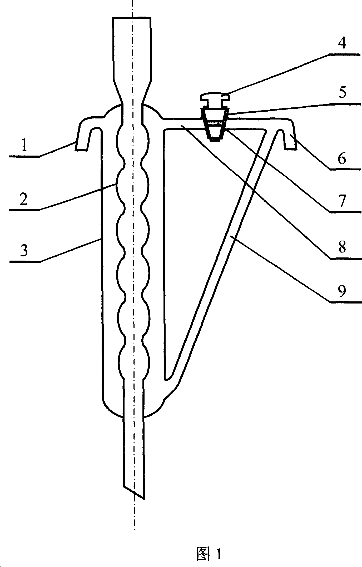
[0011] As shown in Figure 1, the counter-current reflux condenser has an outer pipe 3 and an inner pipe 2 running through the upper and lower ends of the outer pipe 3. There is a water inlet pipe 1 on one side of the upper part of the outer pipe 3, and an exhaust pipe 8 on the other side. There is a valve 5 on the exhaust pipe 8. There is a piston 4 inside the valve 5, and a through hole 7 is opened on the piston 4. The lower part of the outer pipe 3 has a drain pipe 9 extending upwards and its upper end position is not lower than the upper end of the outer pipe 3. An outlet pipe 6 is formed after the upper end of the drain pipe 9 merges with the end of the exhaust pipe 8 . When using the countercurrent reflux condenser for reflux operation, first turn the piston 4 to open the valve 5 to open the exhaust pipe 8, and the cooling water enters the outer pipe 3 ...


PUM


Abstract

The present invention relates to a glass instrument, in particular, it relates to a counter-current reflux condenser pipe. It includes an outer pipe and an inner pipe which is passed through upper and lower two ends of said outer pipe, and it is mainly characterized by that one side of upper portion of said outer pipe is equipped with a water inlet pipe, its another side is equipped with an air vent pipe, on the air vent pipe a valve is set, the lower portion of said outer pipe is equipped with a drain pipe which is upwards extended and whose upper end position is not lower than upper end portion of said outer pipe, the upper end of said drain pipe and the tail end of said air vent pipe are combined and formed into a water outlet pipe. Said invention can change the flowing direction of cooling water and form a counter-current relationship between two fluids in inner pipe and outer pipe so as to greatly raise heat exchange efficiency of condenser pipe and its cooling effect.

Description

technical field [0001] The invention relates to a glass instrument, in particular to a countercurrent reflux condensation tube. Background technique [0002] The condensing tube is an indispensable cooling part in the distillation and reflux device. The existing condensing tube is usually composed of an inner tube and an outer tube, and the outer tube is provided with a water inlet and a water outlet. Its working principle is that the cooled fluid flows through the inner tube, and the water as the coolant flows through the outer tube. The hot and cold fluids exchange heat through the inner tube wall, and the fluid in the inner tube is absorbed by the outer tube. water cooled. The condensing tubes in the reflux device are installed vertically above the flask, and the hot fluid generated in the flask moves upward along the inner tube, and flows back down after being cooled, so it is also called a reflux condensing tube. Since the reflux condenser is installed vertically, if ...

Claims


Application Information

Patent Timeline
Patent Type & Authority Applications(China)
IPC IPC(8): B01L3/16
Inventor 杨晓东肖珊美蔡力玲
Owner JINHUA VOCATIONAL TECH COLLEGE
Why Eureka
Try Eureka