
Column structure dual-wheel foot driving linear ultrasonic motor and electric exciting manner

A linear ultrasonic motor and cylinder technology, applied in the direction of generator/motor, piezoelectric effect/electrostrictive or magnetostrictive motor, electrical components, etc., can solve the problem of small motor output force, low efficiency, and no comparison Solve problems such as fixing methods to achieve the effect of excellent output characteristics of the motor

Inactive Publication Date: 2007-11-14
JIANGSU FENGKE ULTRASONIC MOTORS TECH
View PDF0 Cites 39 Cited by
  • Summary
  • Abstract
  • Description
  • Claims
  • Application Information

AI Technical Summary

Problems solved by technology

At present, linear ultrasonic motors can basically be divided into two forms: thin plate structure and beam or cylindrical structure. Among them, the linear motor with thin plate structure realizes the reciprocation of the mover of the motor by combining the two-phase modes of longitudinal vibration and bending vibration of the plate. Motion, linear ultrasonic motors with thin plate structure mostly use piezoelectric ceramic d 31 This leads to small output force and low efficiency of the motor. In addition, the stator of the thin-plate structure motor does not have a good fixing method; linear motors with beam or cylindrical structures mostly use piezoelectric ceramic d 33 effect to excite the longitudinal vibration of the stator to realize the reciprocating motion of the motor mover. Linear motors with beam or cylindrical structures are mostly driven by a single foot. The effective working period of the stator of the linear ultrasonic motor driven by a single foot is half of the vibration period of the stator. Therefore, the motor less efficient

Method used


Image

  • Column structure dual-wheel foot driving linear ultrasonic motor and electric exciting manner
  • Column structure dual-wheel foot driving linear ultrasonic motor and electric exciting manner
  • Column structure dual-wheel foot driving linear ultrasonic motor and electric exciting manner

Examples


Embodiment Construction

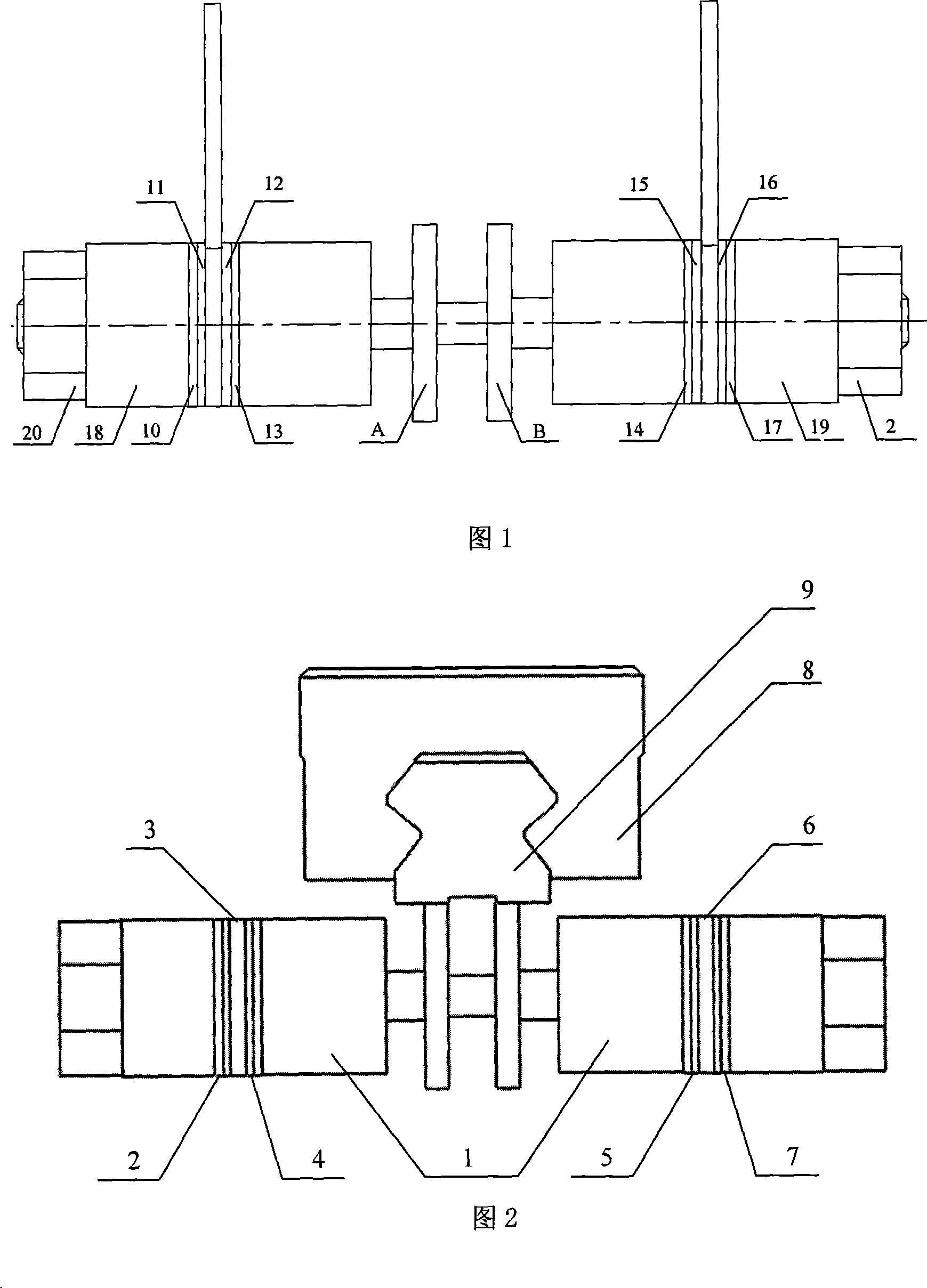
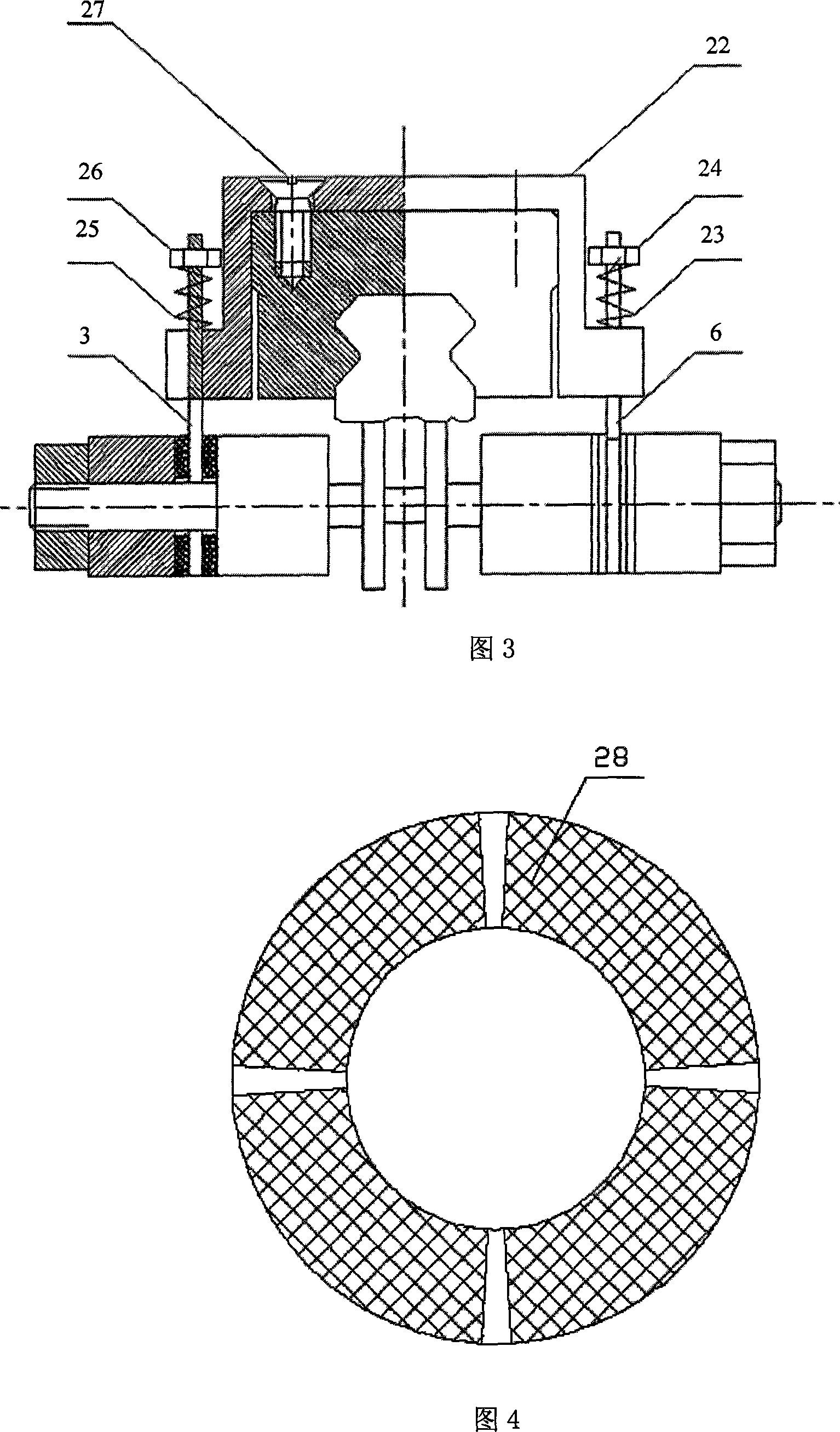
[0022] As shown in FIG. 1 , FIG. 2 and FIG. 3 , the cylindrical double-wheel foot-driven linear ultrasonic motor of the present invention is mainly composed of a stator assembly, a mover assembly and a bracket. The stator assembly is a completely symmetrical structure. The stator assembly consists of four sets of identical piezoelectric ceramics 2, 4, 5, 7 and two supports 3, 6, two pressure blocks 18, 19 and two nuts 20, 21 and It consists of a stepped cylinder 1; on the left side of the stator assembly, the first group of piezoelectric ceramics 4 is clamped between the stepped cylinder 1 and the support 3, and the second group of piezoelectric ceramics 2 is clamped between the support 3 and the pressure Between the blocks 18, the nuts 20 fix the two groups of piezoelectric ceramics 2, 4, the support 3 and the pressing block 18 in the axial direction; each group of piezoelectric ceramics is composed of two identical piezoelectric ceramic rings, and each piezoelectric ceramic ...


PUM


Abstract

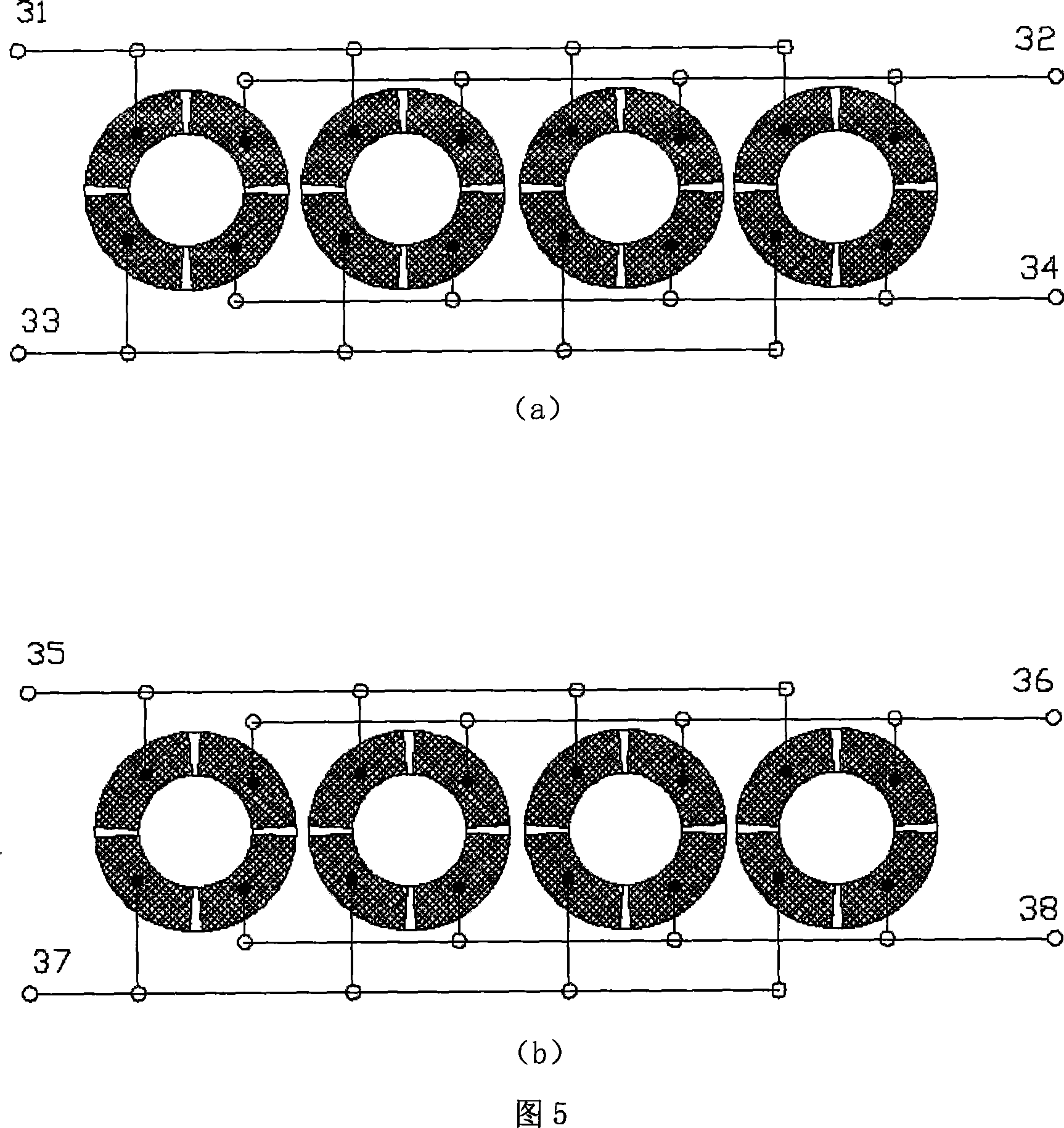
The ultrasound motor is composed of subassemblies of stator, mover and bracket. The stator consists of stepped cylinder, eight pieces of piezoelectric ceramics (PC), pressing block, support and two driving wheels. Electrodes distributed along circumferencial direction evenly are plated on surface of PC. Mover includes slide block and slide bar. The slide bar is contacted to two drive feet of the stator; and the slide bar is fixed on the bracket. The mover is held between bracket and stator. Through supporting effect, springs and nuts on the bracket provide needed pre-compression between stator and mover. Through different fan-shaped electrodes, the drive signal acts on pieces of PC. Under inverse piezo effect, PCs vibrate to excite a natural vibration of stator so as to realize reciprocating rectilinear motion of slide block of mover. Realizing rectilinear motion in two directions of mover, the motor provides features of large output force and speed, and higher efficiency.

Description

1. Technical fields; [0001] The invention relates to a linear ultrasonic motor driven by cylindrical structure double wheel feet and an electric excitation method, belonging to the field of ultrasonic motors. 2. Background technology: [0002] Ultrasonic motor is a new type of power output device that utilizes the inverse piezoelectric effect of piezoelectric ceramics and ultrasonic vibration. At present, linear ultrasonic motors can basically be divided into two forms: thin plate structure and beam or cylindrical structure. Among them, the linear motor with thin plate structure realizes the reciprocation of the mover of the motor by combining the two-phase modes of longitudinal vibration and bending vibration of the plate. Motion, linear ultrasonic motors with thin plate structure mostly use piezoelectric ceramic d 31 This leads to small output force and low efficiency of the motor. In addition, the stator of the thin-plate structure motor does not have a good fixing metho...

Claims


Application Information

Patent Timeline
IPC IPC(8): H02N2/02H02N2/04H02N2/06
Inventor 赵淳生周凤拯金家楣周培
Owner JIANGSU FENGKE ULTRASONIC MOTORS TECH
Learn More