
Split ring resonator bandpass filter, electronic device including said bandpass filter, and method of producing said bandpass filter

A band-pass filter and pass-band technology, which can be used in waveguide-type devices, circuits, electrical components, etc., and can solve problems such as small scale of band-pass filters.

Inactive Publication Date: 2007-11-14
SEIKO EPSON CORP
View PDF0 Cites 18 Cited by
  • Summary
  • Abstract
  • Description
  • Claims
  • Application Information

AI Technical Summary

Problems solved by technology

Also, the bandpass filter must have a fairly small dimension

Method used


Image

  • Split ring resonator bandpass filter, electronic device including said bandpass filter, and method of producing said bandpass filter
  • Split ring resonator bandpass filter, electronic device including said bandpass filter, and method of producing said bandpass filter
  • Split ring resonator bandpass filter, electronic device including said bandpass filter, and method of producing said bandpass filter

Examples


Embodiment Construction

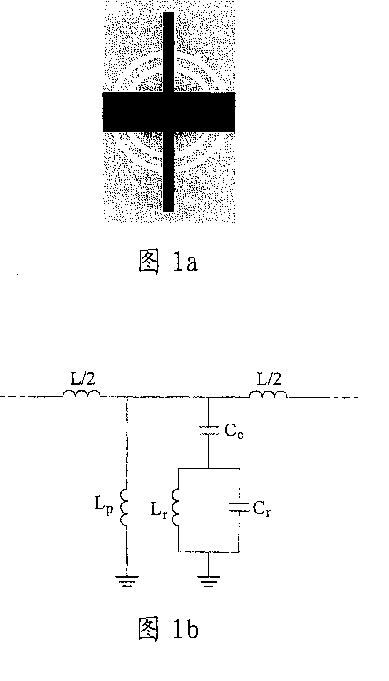
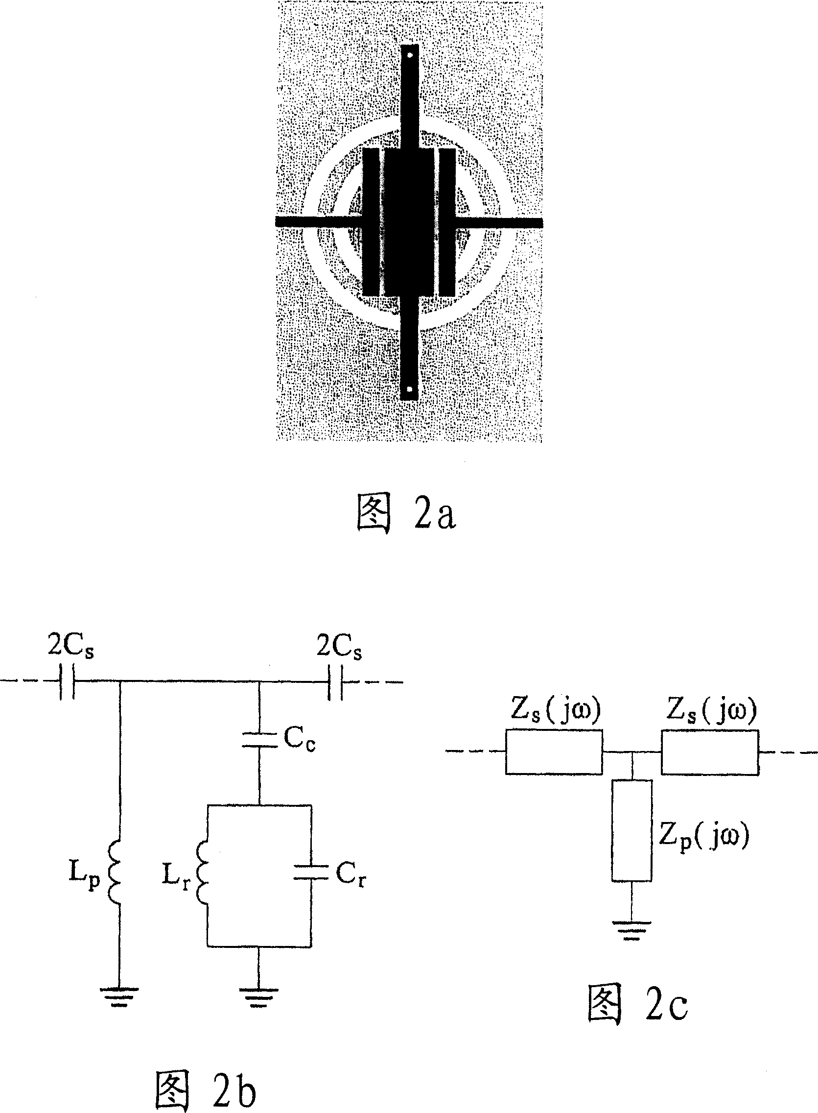
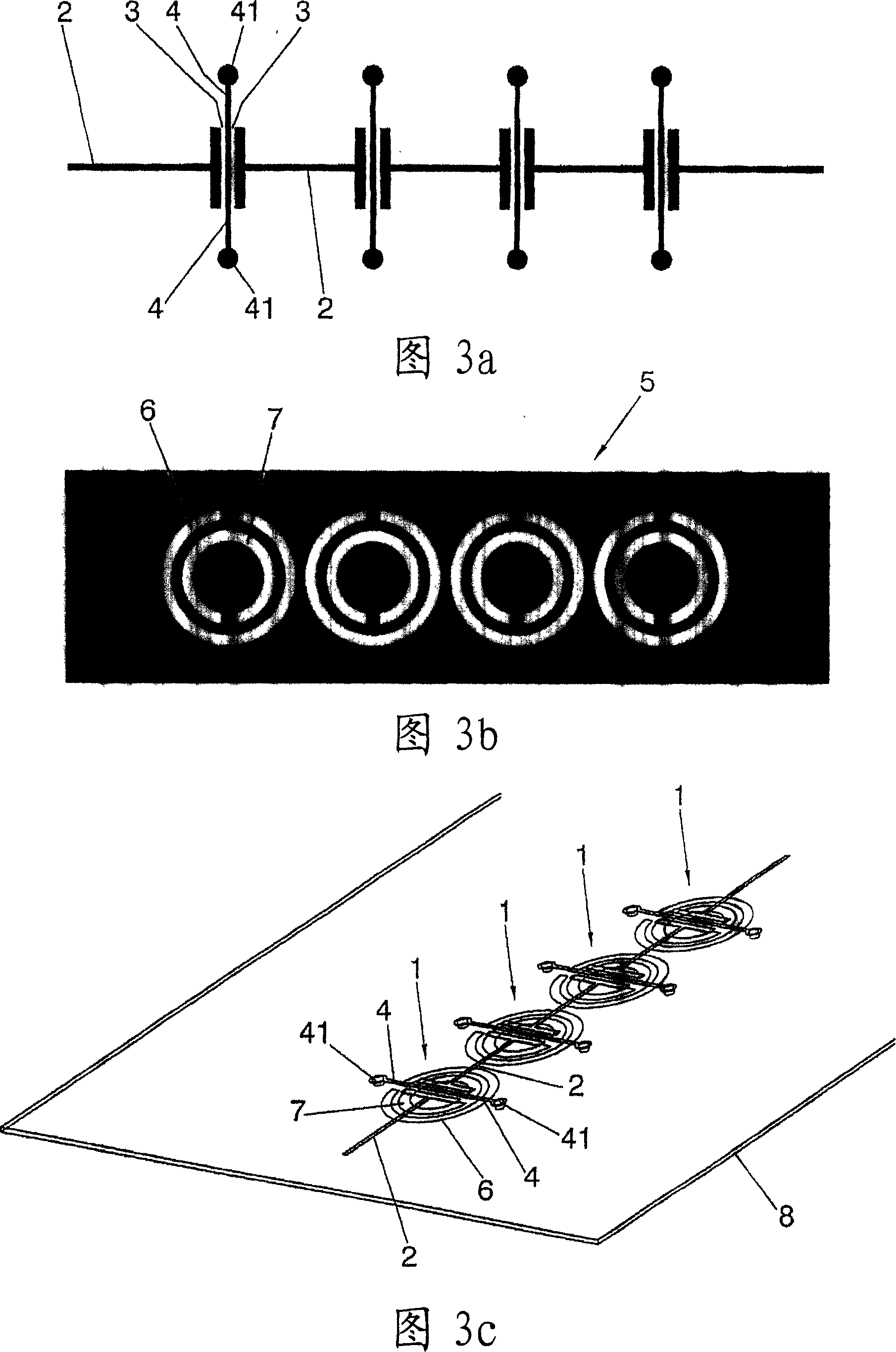
[0081] According to a possible embodiment of the present invention, there is provided a bandpass filter implemented as illustrated in Figures 3a to 3c. The filter comprises four filter units 1 located on a microstrip transmission line comprising a conductor strip 2 and a ground plane 5 . In each filter unit, the conductor strip 2 is interrupted by two capacitive gaps 3 . Between these two gaps are located pairs of metal pins 4 which ground the conductor strip 2 via vias 41 penetrating the dielectric layer 8 separating one layer of the transmission line structure (the layer is illustrated in FIG. 3a and includes conductor strips 2, gaps 3 and stubs 4), and reaches the metal ground layer 5 illustrated in FIG. 3b, in which are etched split rings 6, 7 (the constitute a conventional complementary split ring resonator (CSRR)). Via holes 41 connecting pins 4 to the ground plane can also be seen in Fig. 3c. This basic topology is well known in the prior art, see eg the prior art re...


PUM


Abstract

The bandpass filter comprises transmission line comprising a conductor strip (2), and, in said transmission line, at least one bandpass filter cell, comprising at least one split-rings resonator (6, 7), inductive element (4, 41) and capacitive element (3). The bandpass filter has a frequency response in which at least one passband can be identified. The conductor strip, split-rings resonator(s), inductive element(s) and capacitive element(s) are dimensioned and arranged so that the bandpass filter, for frequencies within said passband, behaves as a left-handed transmission line for at least one range of frequencies within said passband, and as a right-handed transmission line for at least another range of frequencies within said passband, thus providing for a large bandwidth. The invention also relates to an electronic device including the filter, and to a method of producing it.

Description

technical field [0001] The present invention relates to the field of band-pass filters, in particular to band-pass filters based on split-rings resonators and complementary split-rings resonators. Background technique [0002] Bandpass filters are important components in many electronic systems, for example, in radio communication systems. For example, growing interest in ultra-wideband (UWB) communications (at least in part due to the U.S. Federal Communications Commission's 2002 grant of the corresponding spectrum from 3.1 to 10.6 GHz for unrestricted use in indoor and handheld systems ) has led to an increasing focus on UWB components and systems. One of the key components of a UWB system is the UWB bandpass filter, which should exhibit sufficient bandwidth and of course sufficient blocking properties for frequency bands outside the relevant frequency band. In addition, the bandpass filter must have relatively small dimensions. This also applies to bandpass filters out...

Claims


Application Information

Patent Timeline
Patent Type & Authority Applications(China)
IPC IPC(8): H03H7/12H03H3/00
CPCH01P1/20381
Inventor 若尔迪·博纳凯·阿尔瓦塞特胡安·若泽·加西亚·加西亚马尔塔·吉尔·巴尔瓦胡安·费尔南多·马丁·安托林何塞普·伊格斯·卡伊罗·莫林伊格纳西奥·吉尔·加利
Owner SEIKO EPSON CORP
Learn More