Illumination system

A lighting system, translucent technology, applied in the field of lighting systems, can solve the problem of not changing the beam pattern and so on

Inactive Publication Date: 2007-11-14
KONINKLIJKE PHILIPS ELECTRONICS NV
View PDF1 Cites 15 Cited by
  • Summary
  • Abstract
  • Description
  • Claims
  • Application Information

AI Technical Summary

Problems solved by technology

[0005] A disadvantage of the known lighting system is that it is not possible to change the beam pattern emitted by the lighting system

Method used


Image

  • Illumination system
  • Illumination system
  • Illumination system

Examples


Embodiment Construction

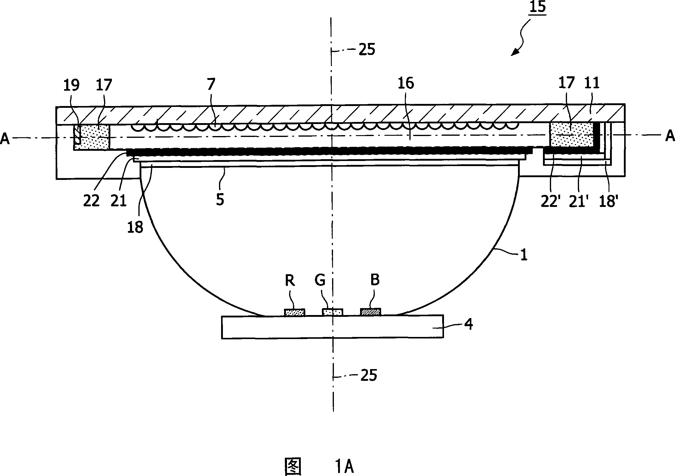
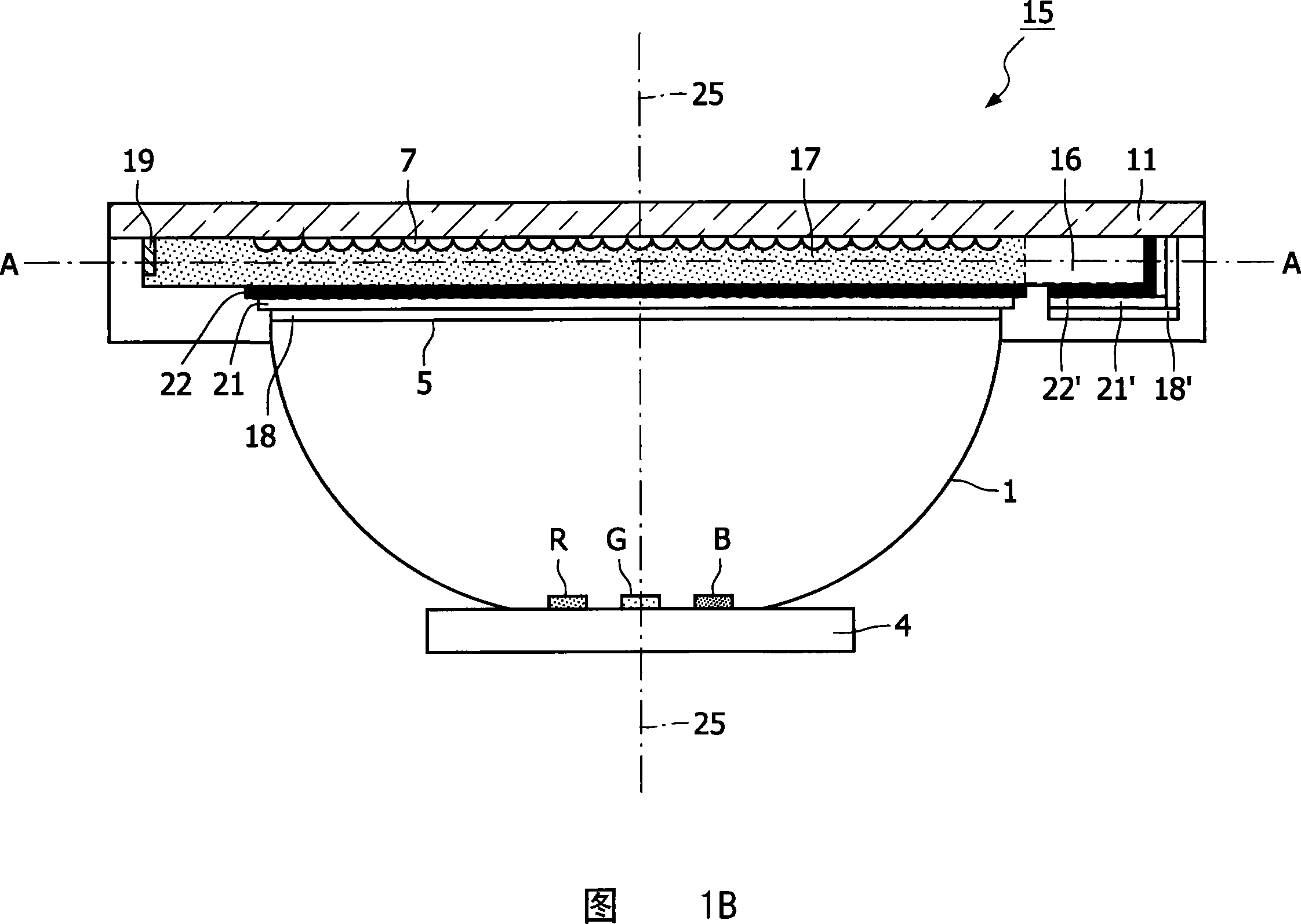
[0037] Fig. 1A schematically shows a cross-sectional view of a first embodiment of an illumination system according to the invention having an active light dispersing structure. Figure IB schematically illustrates a cross-sectional view of an embodiment of the illumination system shown in Figure IA in an operating mode that reduces the effect of light-dispersing structures.

[0038] The lighting system in FIGS. 1A and 1B includes a number of light sources, such as a number of light emitting diodes (LEDs). The LEDs may be light sources of different primary colors, such as the well-known red R, green G or blue B light emitters in the example of FIGS. 1A and 1B . Alternatively, the light emitter may have, for example, amber or cyan as a primary color. These primary colors can be produced directly by the LED chips, or by phosphors under irradiation with light from the LED chips. In the latter case, mixed colors or white light can also be used as a primary color of the lighting s...


PUM


Abstract

An illumination system has a plurality of light emitters (R, G, B) and a light- collimator (1) for collimating light emitted by the light emitters. The light-collimator is arranged around a longitudinal axis (25) of the illumination system. A light-exit window (5) of the light-collimator at a side facing away from the light-emitters is provided with a translucent cover plate (11) provided with a switchable optical element (15) based on electrowetting. The light-exit window of the light-collimator or the translucent cover plate is provided with a light-dispersing structure (7) for broadening an angular distribution of the light emitted by the illumination system. The optical element (15) being switchable in a mode of operation reducing the effect of the light-dispersing structure (7). Preferably, the effect of the light-dispersing structure is substantially counteracted when the switchable optical element operates in the mode of operation reducing the effect of the light-dispersing structure.

Description

technical field [0001] The invention relates to a lighting system comprising a number of light emitters, a light collimator for collimating the light emitted by the light emitters, and a light collimator for widening the angular distribution of the light emitted by the lighting system light dispersion structure. Background technique [0002] Such lighting systems are known per se. In particular it is used for general lighting purposes, such as spotlights, accent lighting, floodlights, and it is used for large-area direct-view light-emitting panels, as in applications such as signs, contour lighting and billboards. In other applications, the light emitted by such an illumination system is routed into an optical waveguide, fiber optic or other beam shaping optics. In addition, such lighting systems are used as backlighting for (image) display devices, such as television receivers and monitors. Such lighting systems can be used as backlights for non-emissive displays such as...

Claims


Application Information

Patent Timeline
Patent Type & Authority Applications(China)
IPC IPC(8): G02B26/02G02B1/06G02B5/02
CPCF21V14/003G02B1/06G02B5/0215F21Y2101/02G02B5/0278G02B26/004F21Y2115/10
Inventor J·P·M·安森斯C·G·A·霍伦
Owner KONINKLIJKE PHILIPS ELECTRONICS NV
Why Eureka
Try Eureka