Compact machine-oil cooler

An oil cooler, compact technology, applied in the direction of machine/engine, gear lubrication/cooling, mechanical equipment, etc., can solve the problems of easy blockage of flow channels, affect the heat exchange performance of the cooler, complex chip structure, etc., and achieve weight reduction , the effect of broadening the cooling capacity and reducing the manufacturing cost

Inactive Publication Date: 2007-11-21
SHANGHAI JIAO TONG UNIV
View PDF1 Cites 8 Cited by
  • Summary
  • Abstract
  • Description
  • Claims
  • Application Information

AI Technical Summary

Problems solved by technology

This type of chip structure is complex, and the flow channels between layers are easy to block, which affects the heat transfer performance of the cooler

Method used


Image

  • Compact machine-oil cooler
  • Compact machine-oil cooler
  • Compact machine-oil cooler

Examples


Embodiment Construction

[0028] The embodiments of the present invention are described in detail below in conjunction with the accompanying drawings: this embodiment is implemented under the premise of the technical solution of the present invention, and detailed implementation methods and processes are provided, but the protection scope of the present invention is not limited to the following implementations example.

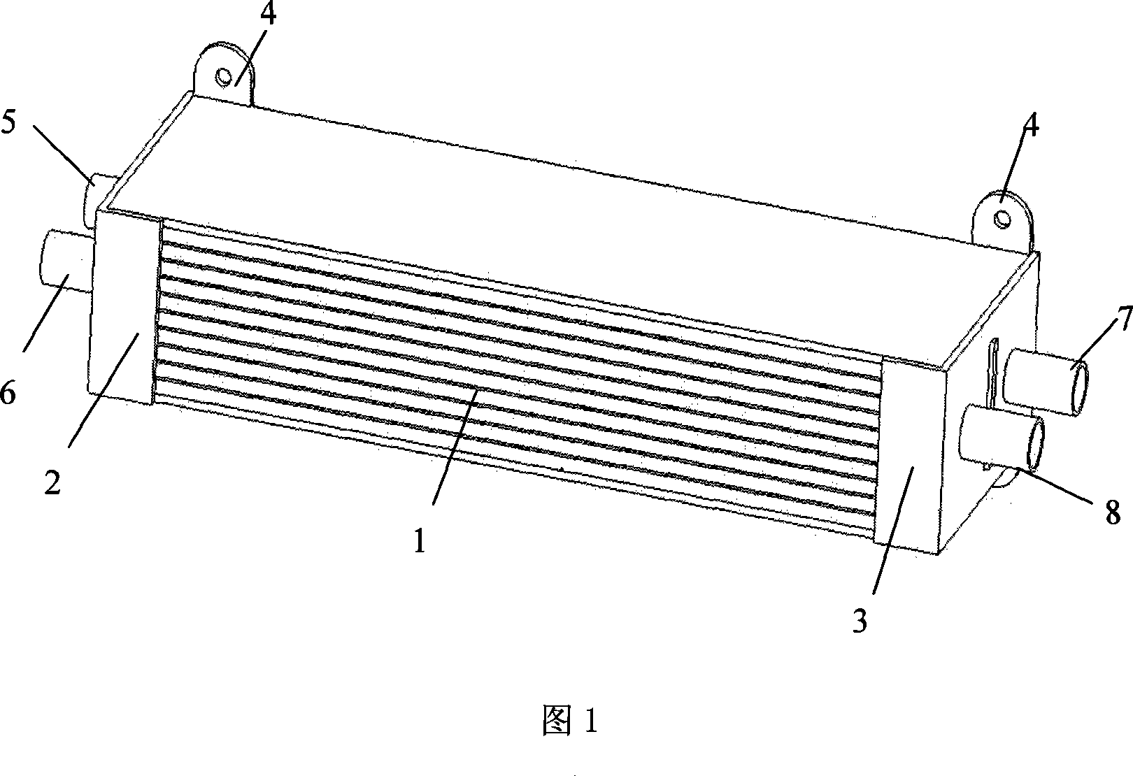
[0029] As shown in FIG. 1 , this embodiment includes a cooler body 1 , an oil chamber 2 and a water chamber 3 . The main body of the cooler 1 is composed of several layers of water passages 9 and several layers of oil passages 10 alternately laminated and brazed. The oil chamber 2 and the water chamber 3 are connected to the main body of the cooler 1 by argon arc welding technology.

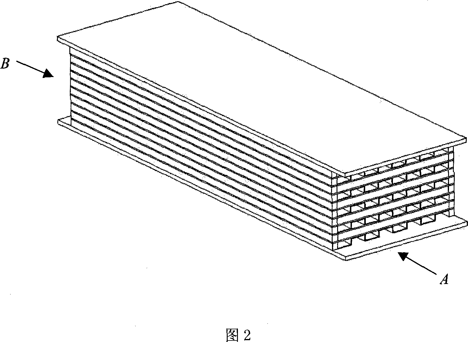
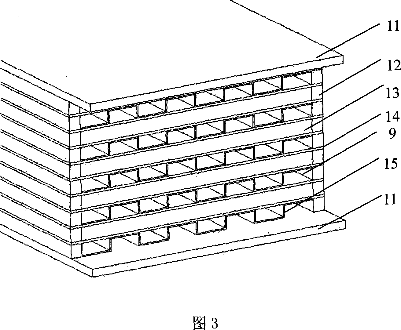
[0030] As shown in Figures 2, 3 and 4, the main body 1 of the cooler is composed of several layers of water passages 9 and several layers of oil passages 10 alternately stacked and brazed to form a whole....


PUM


Abstract

The invention relates to a compact lubricant cooler. It includes the oil room, water room which the side is welded with the in/out oil mouth and in/out mouth. The character is in that: it also includes the cooler body which is welded by many layers of water channel and oil channel and welded with the cooler main body. The invention is used to cool the lubricant in gear-box and engine which has the separately water and oil channel. The structure is compact and the process is simple.

Description

technical field [0001] The invention relates to an oil cooler in the field of mechanical technology, in particular to a compact oil cooler. Background technique [0002] The oil cooler is widely used in mechanical gearboxes or vehicle engines. Its working principle is to circulate and cool the lubricating oil through the convective heat exchange between the coolant side and the oil side, and effectively control the temperature of the engine oil within a certain range. of normal operation. Since the heat transfer coefficient of the oil side of the oil cooler is smaller than that of the water side, that is, the control thermal resistance of the cooler is on the oil side, so the oil side often adopts a compact surface to enhance heat transfer. The power of automobile engines is getting higher and higher, and the trend of engine miniaturization requires that new oil coolers should not only have high-efficiency heat exchange power, low pump power consumption, but also have a com...

Claims


Application Information

Patent Timeline
Patent Type & Authority Applications(China)
IPC IPC(8): F01M5/00F16H57/04
Inventor 郭丽华覃峰陈江平陈芝久
Owner SHANGHAI JIAO TONG UNIV
Why Eureka
Try Eureka