
Method for operation of a compressor supplied by a power converter

A rectifier and compressor technology, applied in the field of compressors, can solve the problems that the detection and control devices cannot respond quickly enough, and achieve the effects of shortening the duration, reducing the strength and prolonging the service life

Active Publication Date: 2007-11-21
SIEMENS AG
View PDF0 Cites 9 Cited by
  • Summary
  • Abstract
  • Description
  • Claims
  • Application Information

AI Technical Summary

Problems solved by technology

In a single-stage compressor, the occurrence of an undesired operating point is so sudden that conventional detection and control devices cannot react fast enough
As a result, the compressor must be overhauled after a limited predetermined number of failures

Method used


Image

  • Method for operation of a compressor supplied by a power converter
  • Method for operation of a compressor supplied by a power converter
  • Method for operation of a compressor supplied by a power converter

Examples


Embodiment Construction

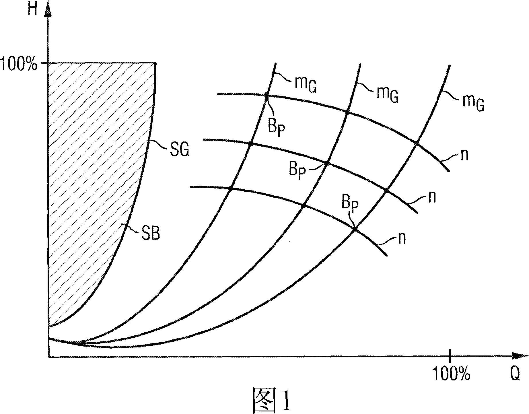
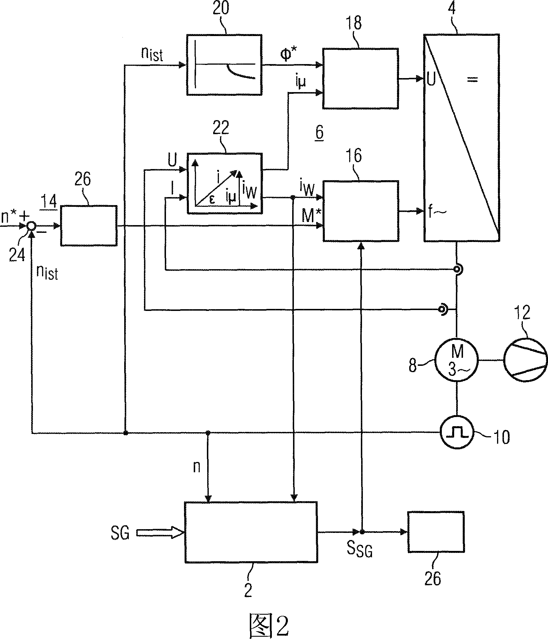
[0023] The H-Q curve diagram of a compressor shown in Figure 1 shows the speed characteristic curve n and the inverse torque characteristic curve m G . Reverse torque characteristic curve m G Each point of intersection of the speed characteristic curve n represents a working point B of a compressor powered by a power rectifier P . Furthermore, this H-Q diagram shows a non-permissible region SB of a compressor powered by a power rectifier, which is separated from the permissible region by a pumping limit line SG, also called "surge limit SG". Under normal circumstances, a compressor only works in the allowable area, among them, the working point B P It lies on an anti-torque characteristic curve adjacent to the surge limit SG. The higher the utilization rate of the compressor, the reverse torque characteristic curve m G The closer it is to the surge limit SG. The surge limit SG is related to the gas density G D Correlation, when the compressor material is given, it is re...


PUM


Abstract

A method for decolorizing and stabilizing alkylphenyl esters of phosphoric acid which comprises contacting the esters with an effective amount of a benzofuranone (e.g., is 5,7-di-t-butyl-3-(3,4 di-methylphenyl)3H-benzofuran-2-one) for a sufficient length of time to decolorize and stabilize the esters against subsequent color formation.

Description

technical field [0001] The invention relates to a method of operating a compressor powered by a power converter. Background technique [0002] Usually, the power consumption, torque and rotational speed of compressors, such as centrifugal compressors and turbo compressors, follow a defined ratio. Variations of these parameters can be represented by a family of characteristic curves. In particular, a volume flow-pressure diagram is used to represent the working state of the compressor. Figure 1 shows such a H-Q curve. Compressors usually only work within a permissible range of the characteristic curve. Except for the shaded area SB, other areas of this characteristic curve family are allowable areas. The shaded area SB represents a non-permissible area SB that the compressor must avoid. If the compressor operates in this non-permissible area SB, damage to the compressor will result. Entry into this non-permissible region SB can be determined by a so-called pump limit li...

Claims


Application Information

Patent Timeline
Patent Type & Authority Applications(China)
IPC IPC(8): F04D27/02
CPCF04D27/0261F04D27/001Y02B30/70
Inventor 阿克塞尔·默滕斯格哈德·尼瑟
Owner SIEMENS AG
Learn More