

Fabric thrashing machine
A technology of dispersing machine and fiber, applied in cleaning machinery, carpet cleaning, floor cleaning, etc., can solve the problems of time-consuming, low efficiency and labor, and achieve the effect of solving low efficiency and improving efficiency
- Summary
- Abstract
- Description
- Claims
- Application Information
AI Technical Summary
Problems solved by technology
Method used
Image

Examples
Embodiment Construction
[0016] The present invention will be further described in detail below in conjunction with the accompanying drawings and embodiments.
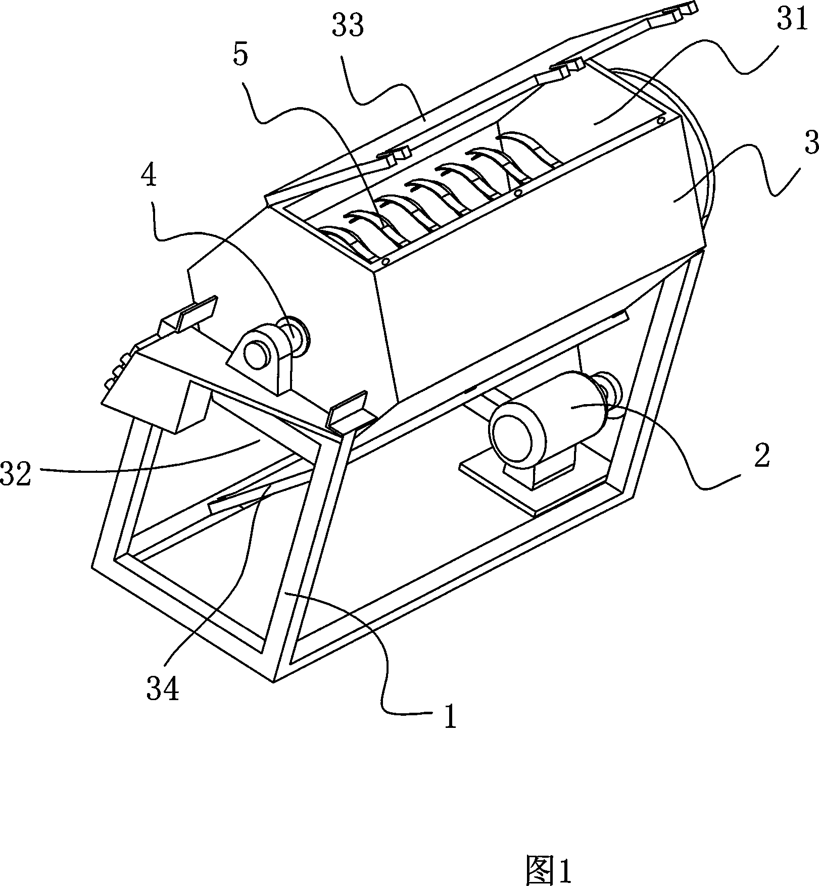
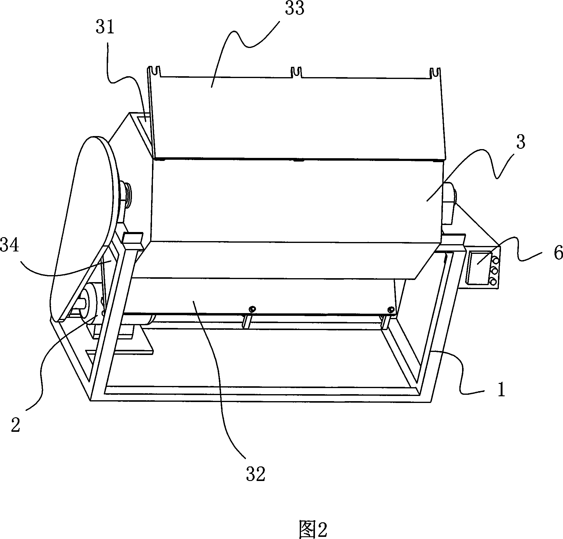
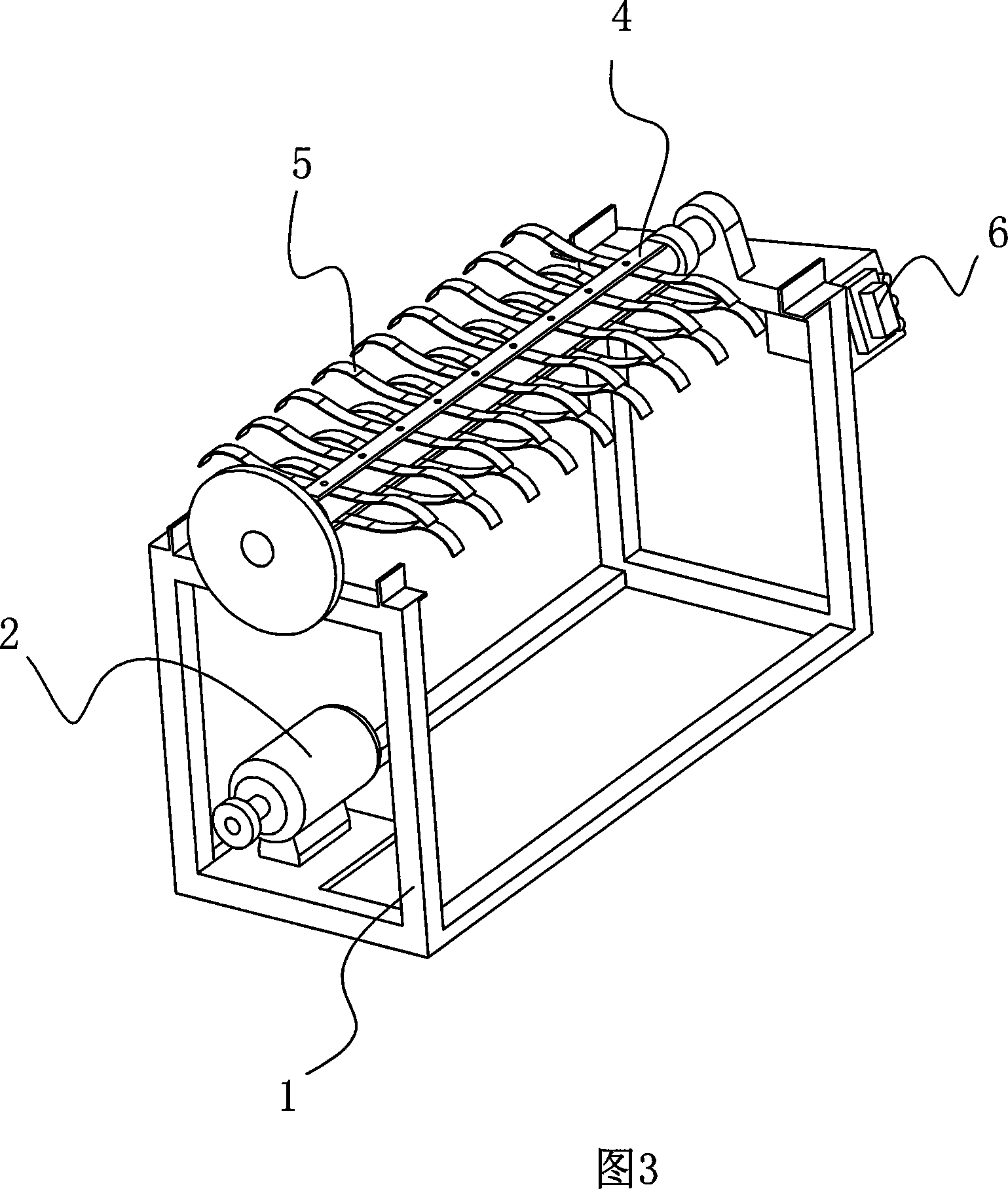
[0017] As shown in Figures 1-4, the fiber breaker of the present invention mainly includes a frame 1, a motor 2, a control device 6, a casing 3, a main shaft 4 and a loose action member 5, wherein the casing 3 has a hexagonal shape Barrel shape, horizontally arranged on the frame 1. An inlet 31 for putting in processed products and an outlet 32 for taking out finished products are respectively provided on the upper and lower parts of the casing 3, and there are cover plates 33, 34 that can be opened and locked at the inlets and outlets.
[0018] The main shaft 4 is located in the inside of the casing 3, wherein the two ends pass through the casing 3 and are installed on two support frames on the frame 1, and the motor 2 drives the main shaft to rotate forward or reversely through a belt and a pulley.
[0019] The control device 3 is fixed o...
PUM
 Abstract
Description
Claims
Application Information