Laser processing machine condensing lens dirt detecting method and device

A laser processing machine and condenser lens technology, applied in the direction of measuring devices, laser welding equipment, metal processing equipment, etc., can solve the problems of complex structure of the processing head and achieve the effect of simple mechanism

Inactive Publication Date: 2007-11-28
YAMAZAKI MAZAK KK
View PDF2 Cites 8 Cited by
  • Summary
  • Abstract
  • Description
  • Claims
  • Application Information

AI Technical Summary

Problems solved by technology

[0008] When using this mechanism, not only the structure of the processing head is complicated, but also the processing of camera data is required

Method used


Image

  • Laser processing machine condensing lens dirt detecting method and device
  • Laser processing machine condensing lens dirt detecting method and device

Examples


Embodiment Construction

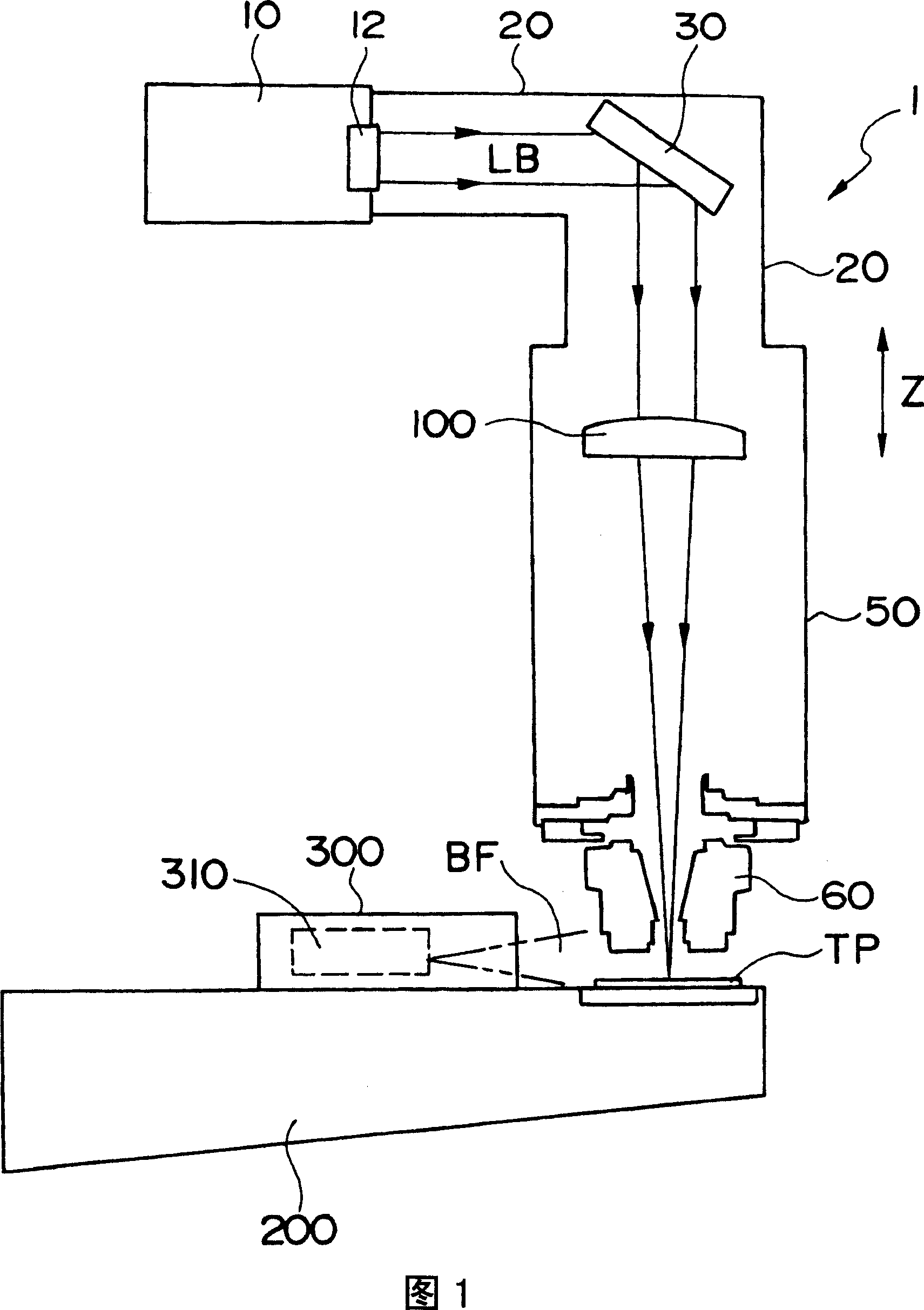
[0016] FIG. 1 is an explanatory view showing the overall configuration of a dirt detection device for a condenser lens of a laser processing machine according to the present invention.

[0017] Reference numeral 1 denotes an overall condenser lens dirt detection device, which includes a light receiving device 300 provided on a partial base 200 of the laser processing machine. This light-receiving device 300 has a light-receiving sensor 310 and detects a strong light called a blue flame BF that occurs when the focus positions of the laser beams condensed on the test piece TP coincide.

[0018] A laser resonator 10 of a laser processing machine outputs a laser beam LB to an optical path 20 through an output lens 12 . A turning mirror 30 and the like are arranged in the optical path 20 to guide the laser beam LB into the machining head 50 .

[0019] With respect to the optical path 20 on the fixed side, the laser head 50 is controlled to move in the Z-axis direction perpendicula...


PUM


Abstract

The invention provides a technology that fouling on condensing lens of laser processing machine is inspected according to the change of focal distance. Condensing lens (100) in machining head (50) is used to condense laser beam (LB) outputted by laser resonator (10). The laser beam irradiates testing part (TP) from laser nozzle (60). The control device of laser processing machine controls processing head (50) to move to Z direction and stores coordinates. If the focus is the same on test part (TP) blue flame (BF) happens. Lighted device (300) receives blue flame and sends signal to the control device. If fouling clings to the condensing lens (100), because heat is stored lens expands and focal distance is shortened. According to the change fouls on condensing lens can be inspected.

Description

technical field [0001] The present invention relates to an automatic detection device for dirt on a condenser lens equipped in a laser gun of a laser processing machine. Background technique [0002] In a laser processing machine, a laser beam oscillated from a laser resonator is supplied to a laser gun for processing through an optical system including a turning mirror, etc., and the laser beam is condensed by a condenser lens in the laser gun so that its focal point is aligned with the center of the workpiece. Consistent near the surface, for processing. [0003] If dirt such as foreign matter adheres to the optical system, condenser lens, etc., it will cause a decrease in processing efficiency. [0004] The following Patent Document 1 discloses a technique for inspecting dirt on an optical system, and Patent Document 2 discloses a technique for monitoring the state of dirt on a condenser lens in a laser gun. [0005] Patent Document 1: Japanese Unexamined Patent Applica...

Claims


Application Information

Patent Timeline
Patent Type & Authority Applications(China)
IPC IPC(8): G01N21/958B23K26/06B23K26/00B23K26/70
Inventor 山崎恒彦宫川直臣
Owner YAMAZAKI MAZAK KK
Why Eureka
Try Eureka