
Apparatus for detecting vital functions, control unit and pulse wave sensor

一种生命机能、脉搏波的技术,应用在传感器、心理学装置、应用等方向,能够解决复杂测量设备等问题

Inactive Publication Date: 2007-12-05
盐见利明
View PDF11 Cites 12 Cited by
  • Summary
  • Abstract
  • Description
  • Claims
  • Application Information

AI Technical Summary

Problems solved by technology

This method requires sophisticated measuring equipment

Method used


Image

  • Apparatus for detecting vital functions, control unit and pulse wave sensor
  • Apparatus for detecting vital functions, control unit and pulse wave sensor
  • Apparatus for detecting vital functions, control unit and pulse wave sensor

Examples


Embodiment Construction

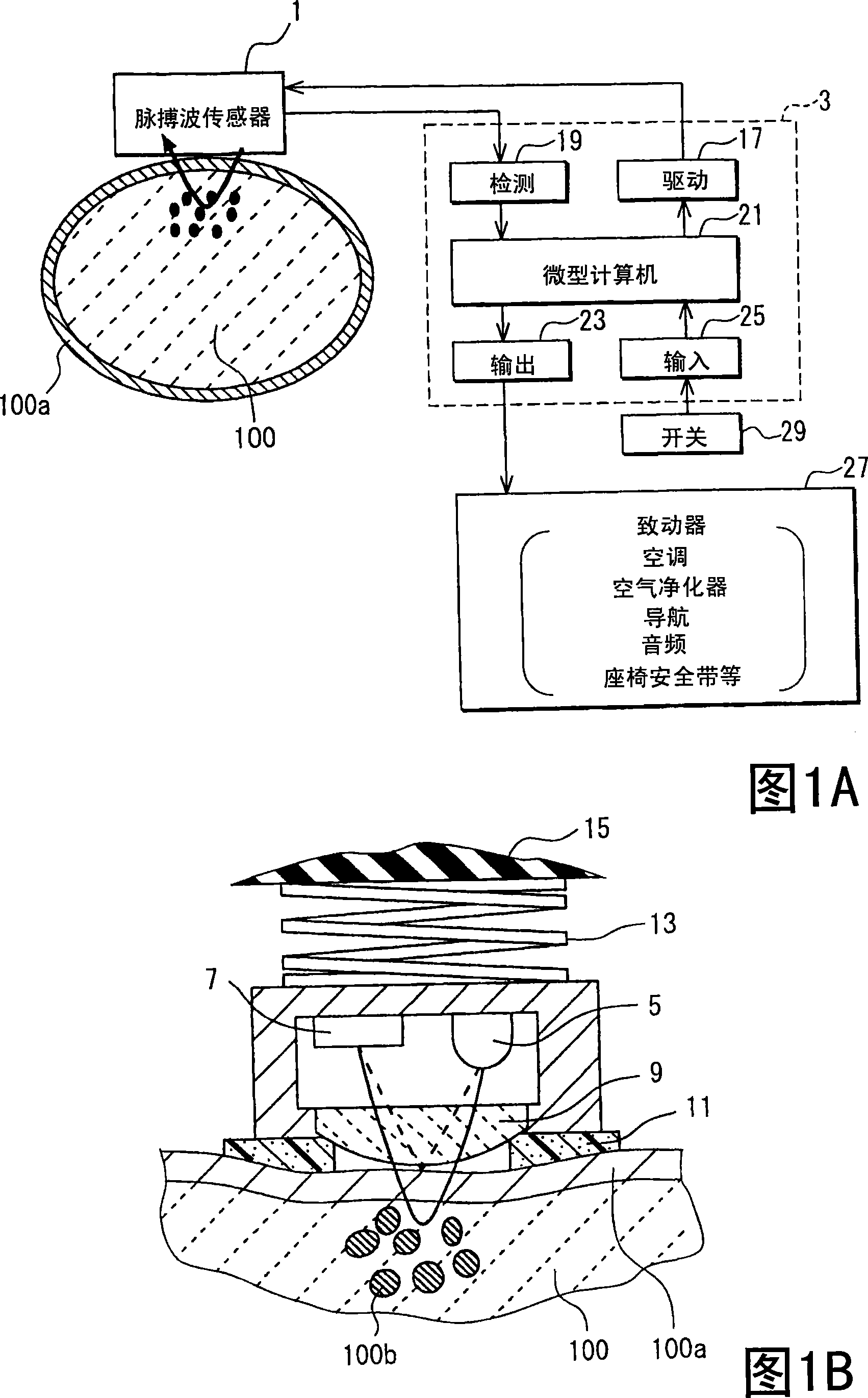
[0090] First, a biometric detection device for detecting a body condition will be described with reference to one embodiment shown in FIGS. 1A and 1B . This device detects vital functions such as coughing or yawning by using the pulse wave sensor 1 . The sensor 1 is attached to a part of the human body 100, such as a finger, palm or wrist, where movement is relatively small. The device also uses a control unit 3 that drives the pulse wave sensor 1 and processes the output from the pulse wave sensor 1 .

[0091] Here, the pulse wave sensor 1 is a reflective type optical sensor (photocapacitive pulse wave sensor), which includes the following elements: a light emitting element (for example, a light emitting diode: green LED) 5, a light receiving element (for example, a photodiode: PD) 7 , and a lens 9 that allows light to pass through and efficiently receives light.

[0092] The pulse wave sensor 1 has a ring-shaped cushioning member (for example, a sponge with a rough end) 11...


PUM


Abstract

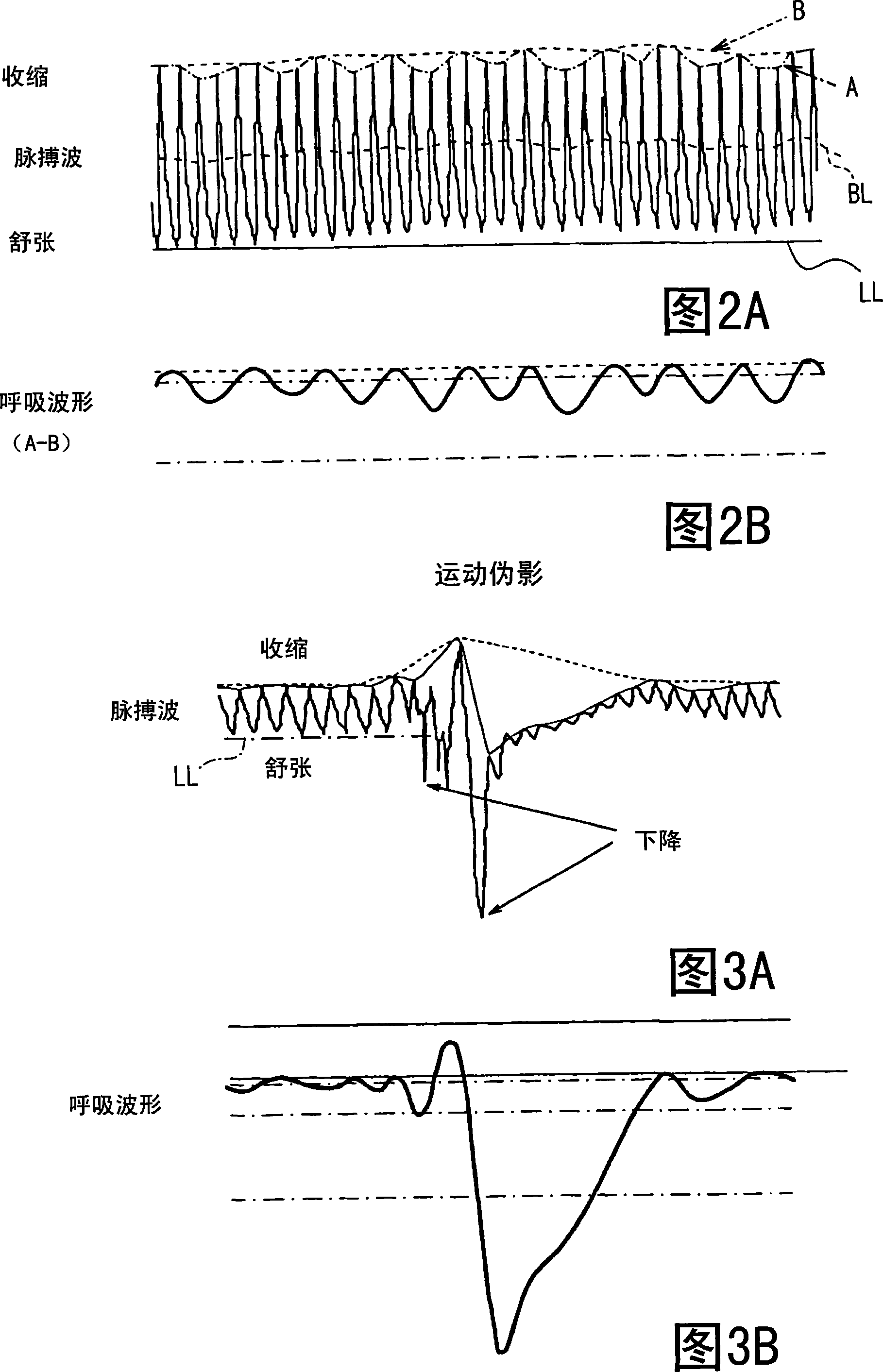
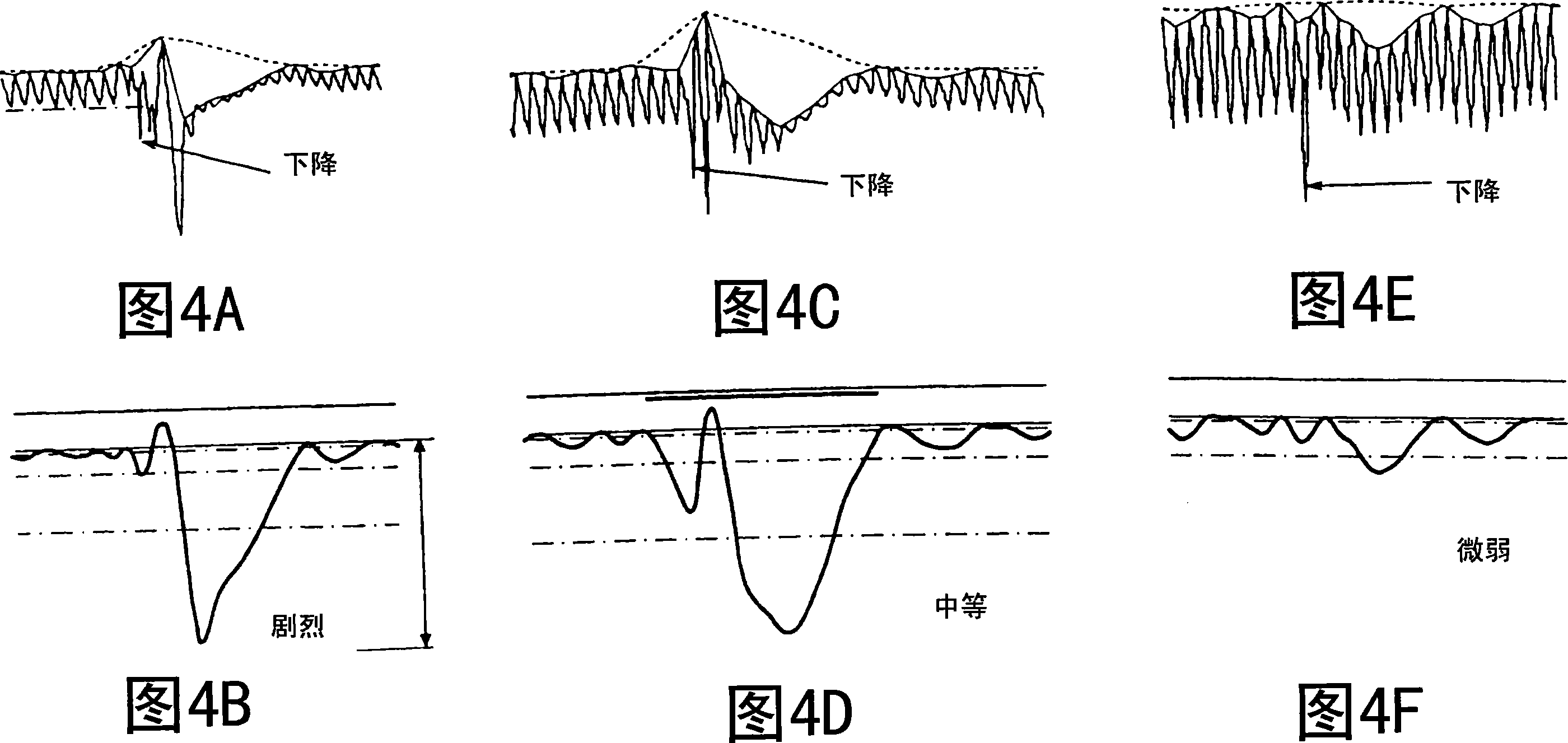
An apparatus for detecting vital functions has a pulse wave sensor (1)attachable to a body and a control unit(3). The control unit checks if amplitude of pulse wave signals produced from the pulse wave sensor (1)varies. The control unit further checks if a large change in the amplitude during a systolic phase of a pulse wave corresponding to the systolic phase of the heart. If a first large change in the amplitude during a diastolic phase of a pulse wave corresponding to the diastolic phase of the heart, it is highly probable that a motion artifact has occurred. Therefore, a motion artifact flag is set. Next, it is checked if the amplitude in the next diastole is changing by more than 30%. If it is presumed that the occurrence of cough is highly probable, a cough flag is set. If it is neither the motion artifact nor the cough, then a yawn flag is set.

Description

technical field [0001] The present invention relates to devices for detecting vital functions, ie, biometric conditions, such as coughing and yawning, using an easily mounted pulse wave sensor. Background technique [0002] Nasal thermal sensors, nasal pressure sensors, chest strap sensors, etc. are used as respiratory system monitors to detect breathing, coughing, and yawning. [0003] For example, regarding measurement of cough, various devices of sprio-breathing flowmeter (Patent Document 1), thyroid signal (Patent Document 2) and catheter vibration (Patent Document 3) are available. These measuring devices and measuring methods are so complex that conditions such as coughing cannot be easily measured in private homes or vehicles. [0004] As a simpler technique, it is proposed to use a graph of a voice signal detected by a microphone (Patent Document 4), or a voice signal and a sound pressure level detected by a microphone (Patent Document 5). The accuracy of this dete...

Claims


Application Information

Patent Timeline
Patent Type & Authority Applications(China)
IPC IPC(8): A61B5/08A61B5/16
CPCA61B5/6826A61B5/0059A61B5/087A61B5/6838A61B5/0823A61B5/02416
Inventor 难波晋治盐见利明
Owner 盐见利明
Learn More