
Ultrasonic diagnostic apparatus, ultrasonic diagnostic method, and control processing program for ultrasonic diagnostic apparatus

A diagnostic device, ultrasonic technology, applied in the direction of acoustic wave diagnosis, infrasonic wave diagnosis, ultrasonic/sonic wave/infrasonic wave diagnosis, etc., which can solve the problem of difficult tracking of sampling marks

Active Publication Date: 2007-12-05
TOSHIBA MEDICAL SYST CORP
View PDF2 Cites 26 Cited by
  • Summary
  • Abstract
  • Description
  • Claims
  • Application Information

AI Technical Summary

Problems solved by technology

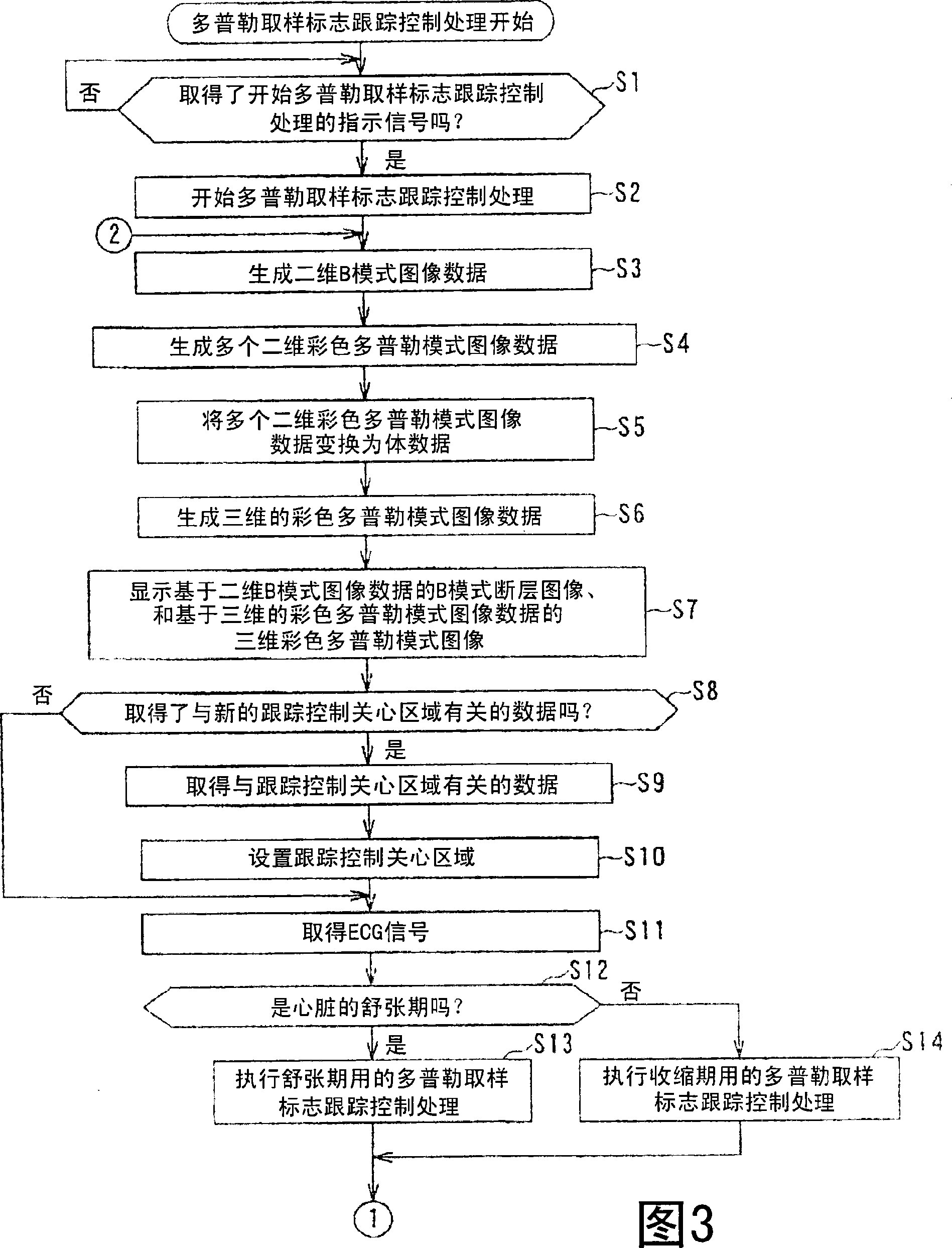
[0011] However, in the ultrasonic diagnostic apparatuses proposed in JP-A-6-217975 and JP-A-2003-523250, automatic tracking of a plurality of ultrasonic vibrators arranged in a one-dimensional array in a two-dimensional tomographic plane is used. Although it is possible to track the movement of blood vessels in the two-dimensional slice, since the blood vessels in the subject move three-dimensionally in the depth direction of the slice, there is a possibility that the blood vessel you want to observe moves in the depth direction relative to the slice. In the case of movement, it is difficult to track the sampling mark in conjunction with the movement of the blood vessel
[0012] In particular, in the case of performing a diagnosis after administering a drug to a subject, since the blood vessels in the subject move three-dimensionally and more than usual, including the depth direction of the tomographic plane, the movement of the blood vessel desired to be observed Coordinated to make sampling flags more difficult to track

Method used


Image

  • Ultrasonic diagnostic apparatus, ultrasonic diagnostic method, and control processing program for ultrasonic diagnostic apparatus
  • Ultrasonic diagnostic apparatus, ultrasonic diagnostic method, and control processing program for ultrasonic diagnostic apparatus
  • Ultrasonic diagnostic apparatus, ultrasonic diagnostic method, and control processing program for ultrasonic diagnostic apparatus

Examples


no. 1 approach

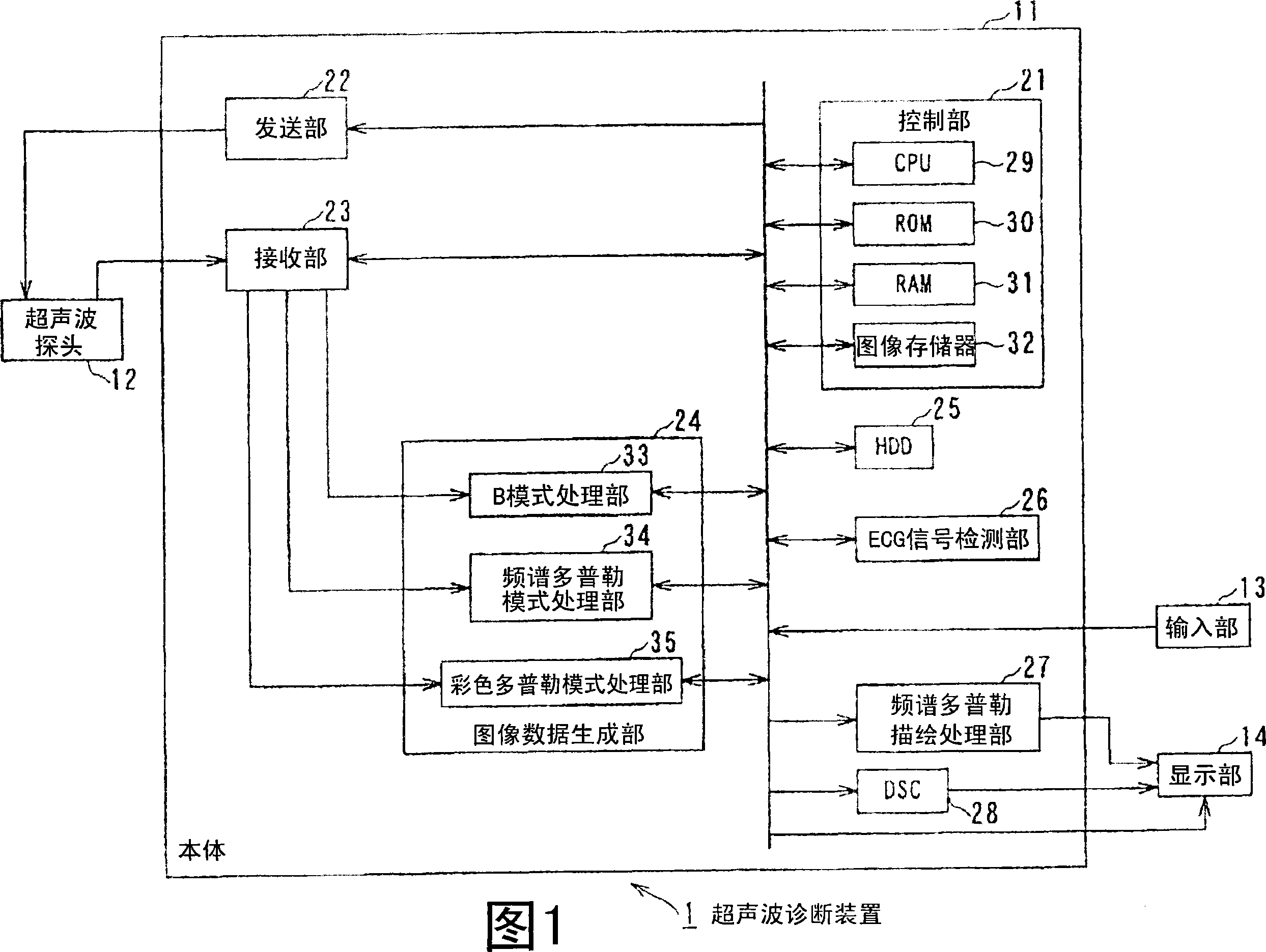
[0046] FIG. 1 shows the internal structure of an ultrasonic diagnostic apparatus 1 to which the present invention is applied.

[0047] The ultrasonic diagnostic apparatus 1 is composed of a main body 11 , an ultrasonic probe 12 connected to the main body 11 via a cable, an input unit 13 and a display unit 14 .

[0048] As shown in FIG. 1 , the main body 11 of the ultrasonic diagnostic apparatus 1 is composed of a control unit 21, a transmitting unit 22, a receiving unit 23, an image data generating unit 24, an HDD (hard disk drive) 25, an ECG (electrocardiogram) signal detecting unit 26, a multi-spectrum The Puler rendering processing unit 27 and a DSC (Digital Scan Converter) 28 are configured.

[0049] The control unit 21 , the transmitting unit 22 , the receiving unit 23 , the image data generating unit 4 , the HDD (hard disk drive) 25 , the ECG signal detecting unit 26 , the spectral Doppler drawing processing unit 27 and the DSC 28 are included in the main body 11 of the ...

no. 2 approach

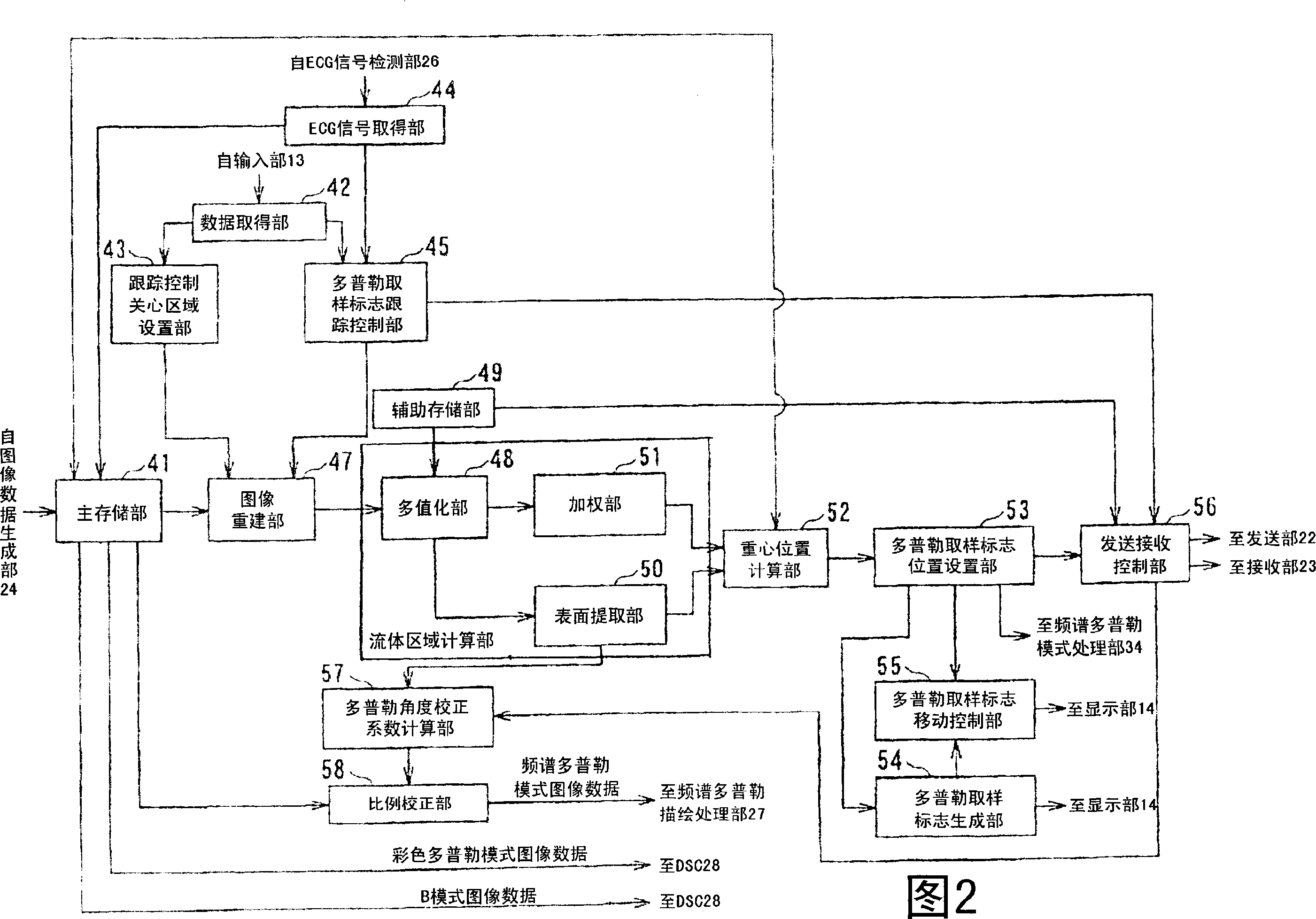
[0252] FIG. 19 shows a configuration in a second embodiment of functions executable by the ultrasonic diagnostic apparatus 1 of FIG. 1 . The same is true for the configuration of the ultrasonic diagnostic apparatus 1 in FIG. 1 , and since this description is redundant, its description is omitted. The parts corresponding to the configuration of the ultrasonic diagnostic apparatus 1 in FIG. 2 are given the same reference numerals, and the description thereof is omitted because it is redundant.

[0253] According to the control of the Doppler sampling mark tracking control part 45, the statistical operation part 59 reads out the Doppler sampling mark position setting data stored in the main storage part 41, and sets the data according to the read Doppler sampling mark position setting data. , to perform statistical calculation processing.

[0254] Specifically, by executing the Doppler sampling mark tracking control process 20 times, for example, at the position where 20 Doppler...


PUM


Abstract

The invention provides an ultrasonic diagnostic equipment, an ultrasonic diagnostic method and a control process of the ultrasonic diagnostic equipment. A multi-thresholding unit performs a multi-thresholding on the volume data of the blood flow speed on the basis of a reference value related to the blood flow speed. A surface extraction unit extracts a surface of the blood flow on the basis of the multi-threshold volume data. A weighting unit performs a weighting used for calculating the position of the center of gravity for the blood flow region formed by the blood flow surface. A center of gravity position calculation unit calculates a position of the center of gravity of the blood flow region the Doppler sample marker position setting unit sets the position of the Doppler sample marker to the position of the center of gravity for the blood flow region. A Doppler sample marker movement control unit controls movement of the Doppler sample marker on the basis of the Doppler sample marker position setting data. The invention makes a sample marker of a spectrum Doppler method to follow three-dimensional movement of a desired blood vessel accurately and easily.

Description

technical field [0001] The present invention relates to an ultrasonic diagnostic device, an ultrasonic diagnostic method, and a control processing program for the ultrasonic diagnostic device, and in particular to an ultrasonic diagnostic device, an ultrasonic diagnostic method, and an ultrasonic diagnostic device capable of tracking the sampling marks of spectral Doppler in cooperation with the movement of blood vessels Control handler. Background technique [0002] In recent years, an ultrasonic diagnostic device capable of displaying tomographic images (B-mode tomographic images) and blood flow information in real time has been proposed by using both the ultrasonic Doppler method and the ultrasonic pulse-echo method. [0003] The ultrasound Doppler method used together with the ultrasound pulse-echo method can be broadly classified into the spectral Doppler method which displays the temporal change of the Doppler frequency corresponding to the velocity of the blood flow, ...

Claims


Application Information

Patent Timeline
Patent Type & Authority Applications(China)
IPC IPC(8): A61B8/06G05B19/00G06T5/00
CPCA61B8/06A61B8/0883A61B8/0891A61B8/488A61B8/543G01S7/52063G01S7/52073G01S7/52085G01S15/8979
Inventor 泻口宗基
Owner TOSHIBA MEDICAL SYST CORP
Learn More