
Variable displacement, constant (air density) compression ratio, constant air/fuel ratio and non air throttle reciprocating engine

A technology of air density and engine, applied in the direction of engine components, engine control, machine/engine, etc.

Inactive Publication Date: 2007-12-05
兰永柱
View PDF0 Cites 4 Cited by
  • Summary
  • Abstract
  • Description
  • Claims
  • Application Information

AI Technical Summary

Problems solved by technology

Upper and lower cylinder moving device
The simultaneous application of four independent inventions on the engine solves the problem of the engine completing the suction stroke under negative pressure, solves the quasi-constant compression ratio of air density under different working conditions, and the quasi-constant air-fuel ratio

Method used

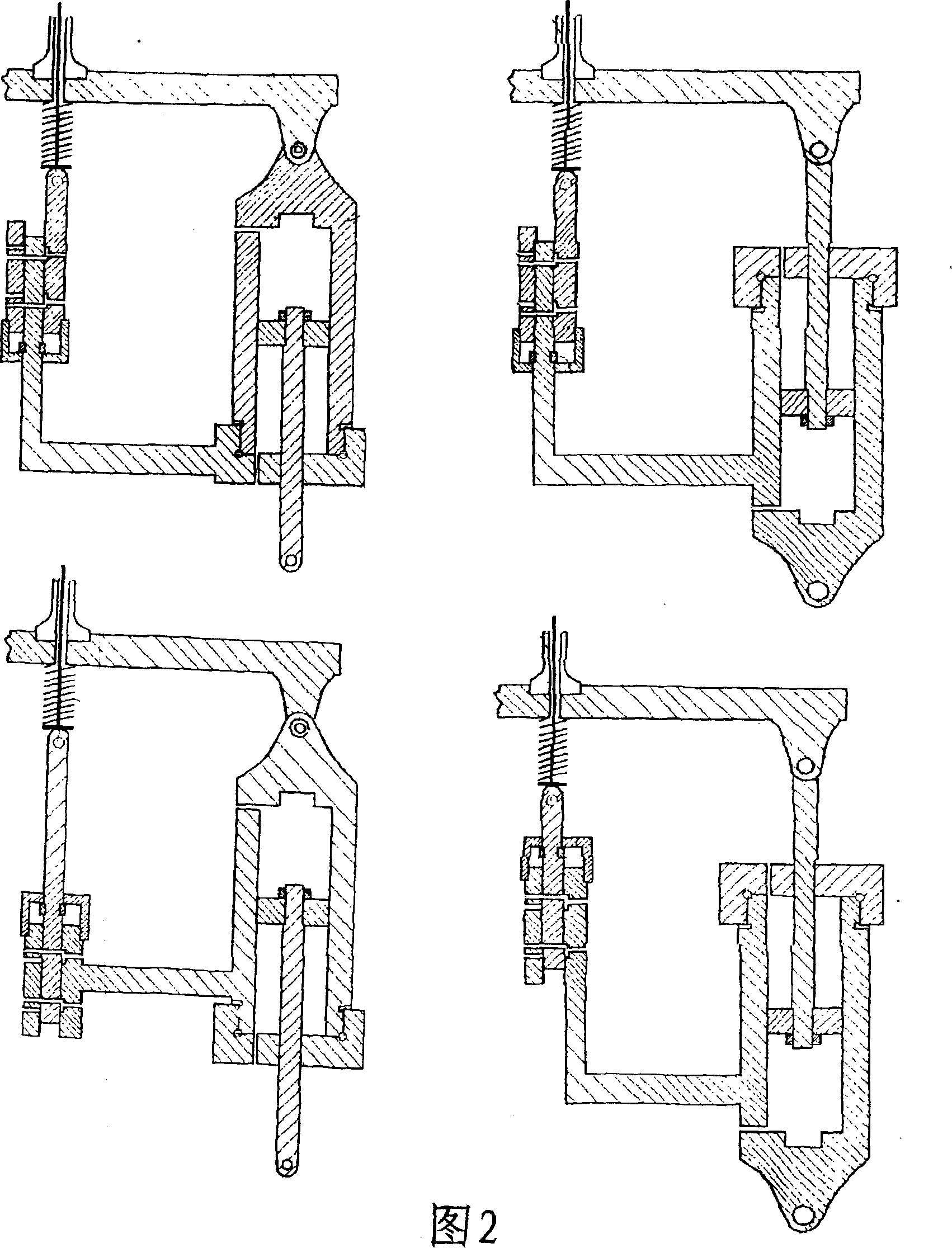
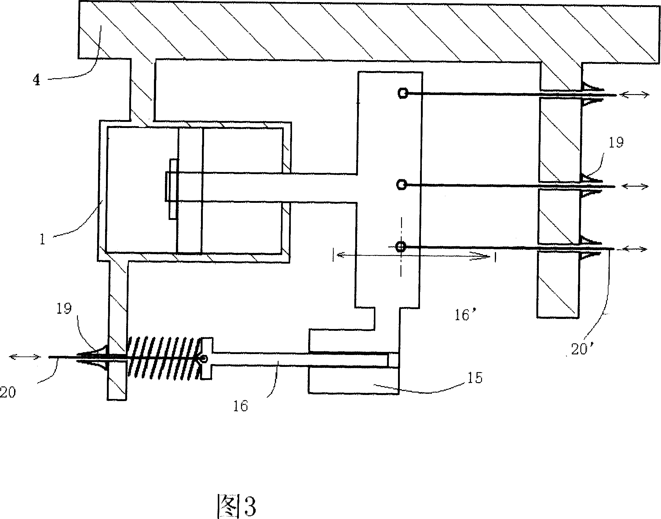

Image

  • Variable displacement, constant (air density) compression ratio, constant air/fuel ratio and non air throttle reciprocating engine
  • Variable displacement, constant (air density) compression ratio, constant air/fuel ratio and non air throttle reciprocating engine
  • Variable displacement, constant (air density) compression ratio, constant air/fuel ratio and non air throttle reciprocating engine

Examples


Embodiment Construction

[0025] Simultaneously apply multiple synchronous linkage displacement devices and upper and lower cylinder moving devices on one engine. Linked combined camshaft mechanism, quasi-constant air-fuel ratio oil supply system.

[0026] Describe the specific embodiment of the present invention in detail with reference to accompanying drawing

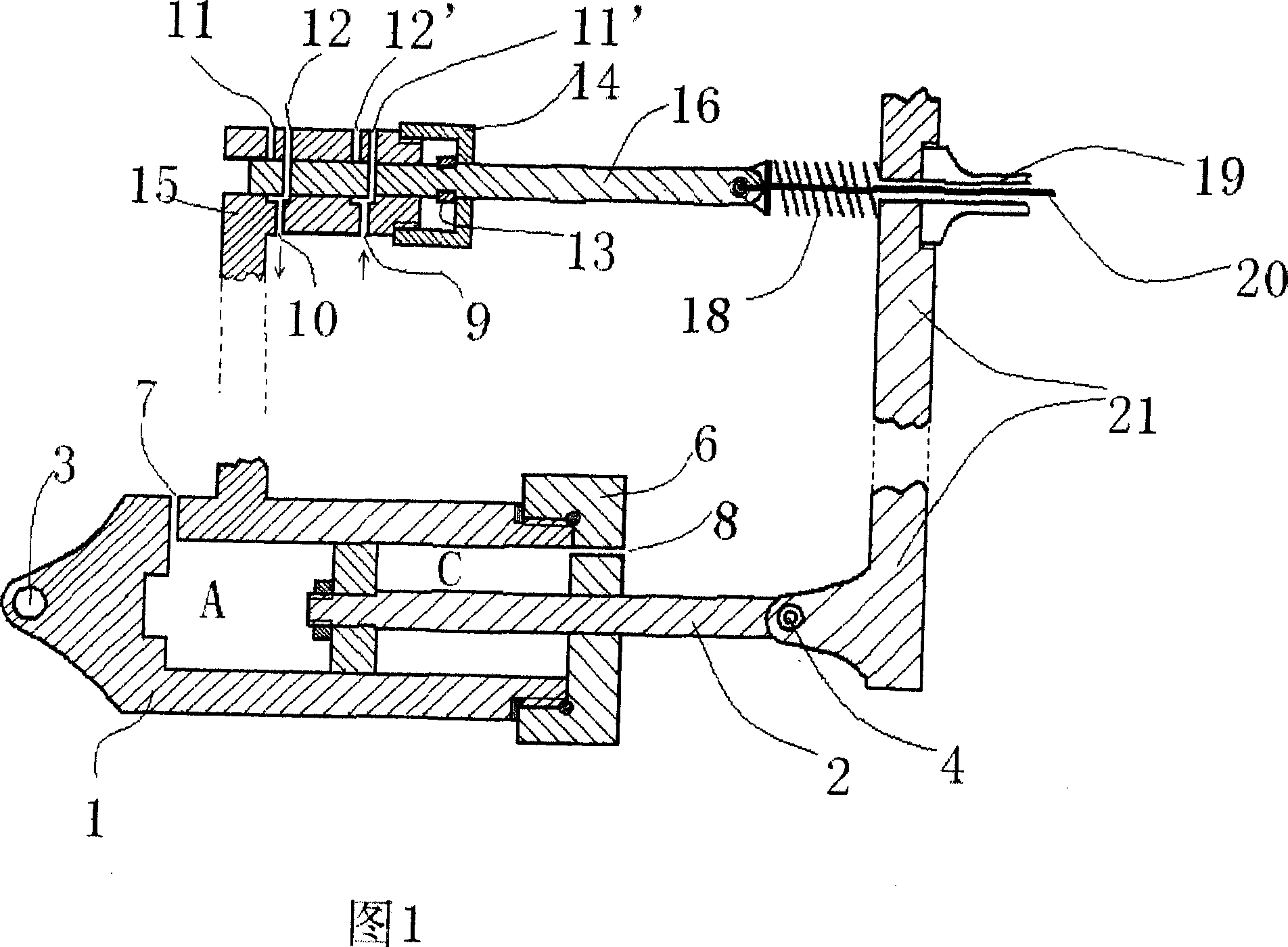
[0027] The preferred implementation of the displacement device is shown in Figure 1. The displacement device is to move the distance between the two parts of a certain system of the engine by manipulation. The follow-up reversing positioning valve is composed of a valve body 15, a plug rod 16, a limiting chamber 5, and a limiting snap ring 13.

[0028] The preferred embodiment of displacement device is as follows:

[0029] The valve body 15 of the following reversing positioning valve is rigidly connected with the cylinder body 1 of the oil cylinder and can move accordingly. The limit cavity 5 is a constant space between the end cover 14 and...


PUM


Abstract

The engine in this invention has five strokes of sucking, exhaling, pressing, bursting and eliminating. The sucking and exhaling divide the sucking stroke of the existing engine. The engine power is adjusted by the long-short exhaling stroke which is resolved by the coupled and combined camshaft mechanism. The engine saves the suction stroke consuming and reduces the emission without installing the air throttle. The ratio of the upper center capacity and the inflatable amount of the cylinder is kept as a constant by moving the upper and lower cylinders and the camshaft mechanism synchronously. The relative position between the upper and lower cylinders / the camshaft mechanism and the axle core under different work conditions can be detected by the sensor. The detecting value is used to calibrate the fuel supplies. The relationship between the cylinder inflatable amount and the cam mandrel 36 moving amount appears nonlinear by adjusting the shape the cam mandrel driving groove 43. It selectively optimizes the quasi-sidereal compression ratio and air-fuel ratio under different work conditions, which is more energy-saving and environmental protection than the traditional engines.

Description

[0001] TECHNICAL FIELD: This invention relates to reciprocating engines. Background technique [0002] The four-stroke throttle-controlled reciprocating engine has been in operation for hundreds of years and is one of the cornerstones of modern civilization. The research and improvement work on it has never stopped, and a large number of new technologies are used in it, and modern engines have been perfected day by day. But the so-called perfection is based on the inherent working mode. Its original and existing working mode is as follows: the four-stroke operation mode marked by suction pressure explosion, the throttle valve controls the cylinder air intake to adjust the engine operating conditions, and there is a fixed cylinder top dead center volume , the intake valve closes at a fixed angle. This kind of engine has disadvantages. The throttle control means that the suction stroke is carried out under negative pressure conditions. The suction stroke of most engines is car...

Claims


Application Information

Patent Timeline
Patent Type & Authority Applications(China)
IPC IPC(8): F01L5/14F01L9/02F02D15/04F01L9/10
Inventor 兰永柱
Owner 兰永柱
Learn More