
Wind power generation plant of delivery vehicle

A technology for wind power generation devices and vehicles, which is applied to wind power engines, wind power motor combinations, wind power engines at right angles to the wind direction, etc., and can solve problems such as difficulty

Inactive Publication Date: 2007-12-05
HIWIN TECH
View PDF0 Cites 0 Cited by
  • Summary
  • Abstract
  • Description
  • Claims
  • Application Information

AI Technical Summary

Problems solved by technology

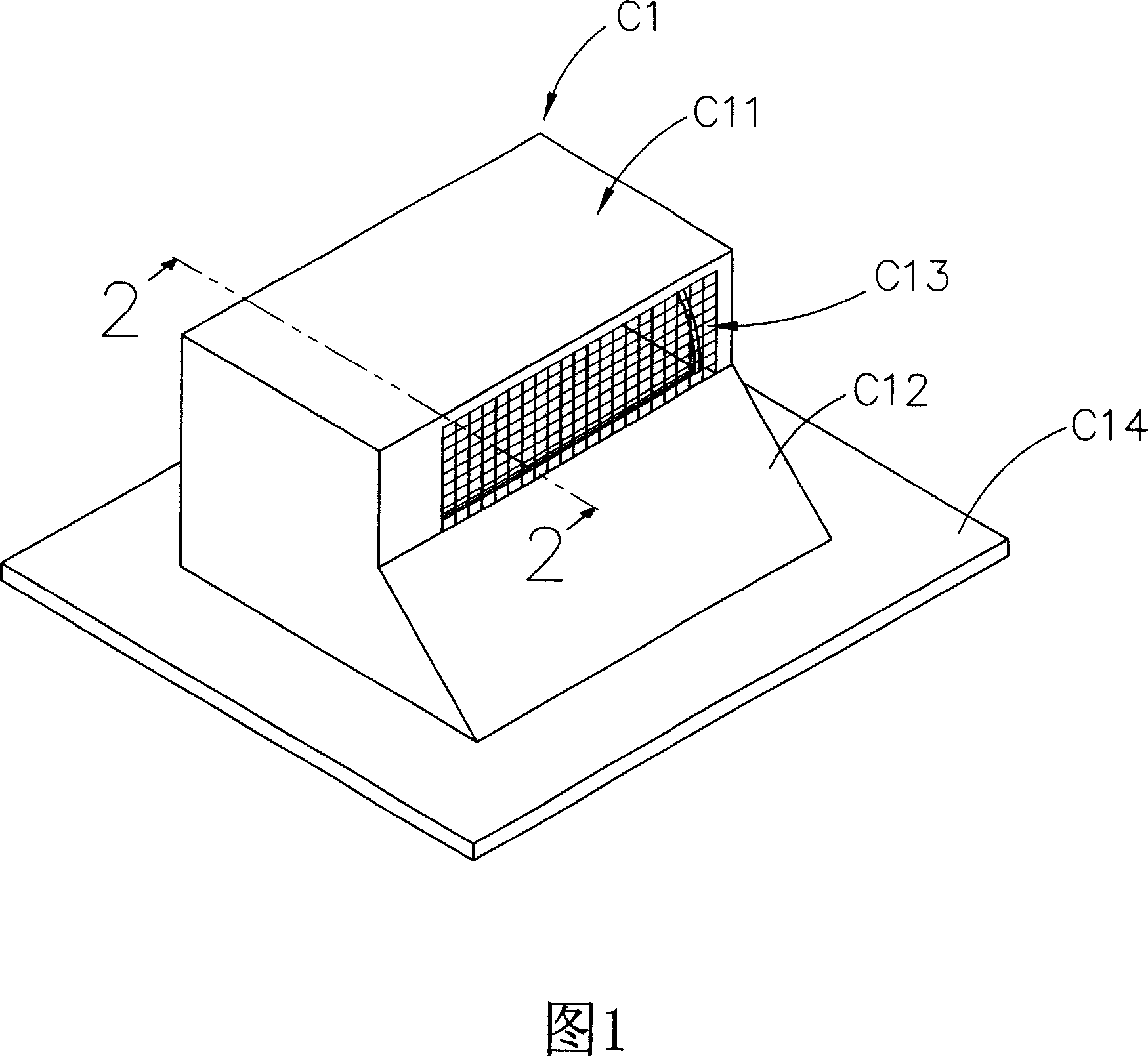
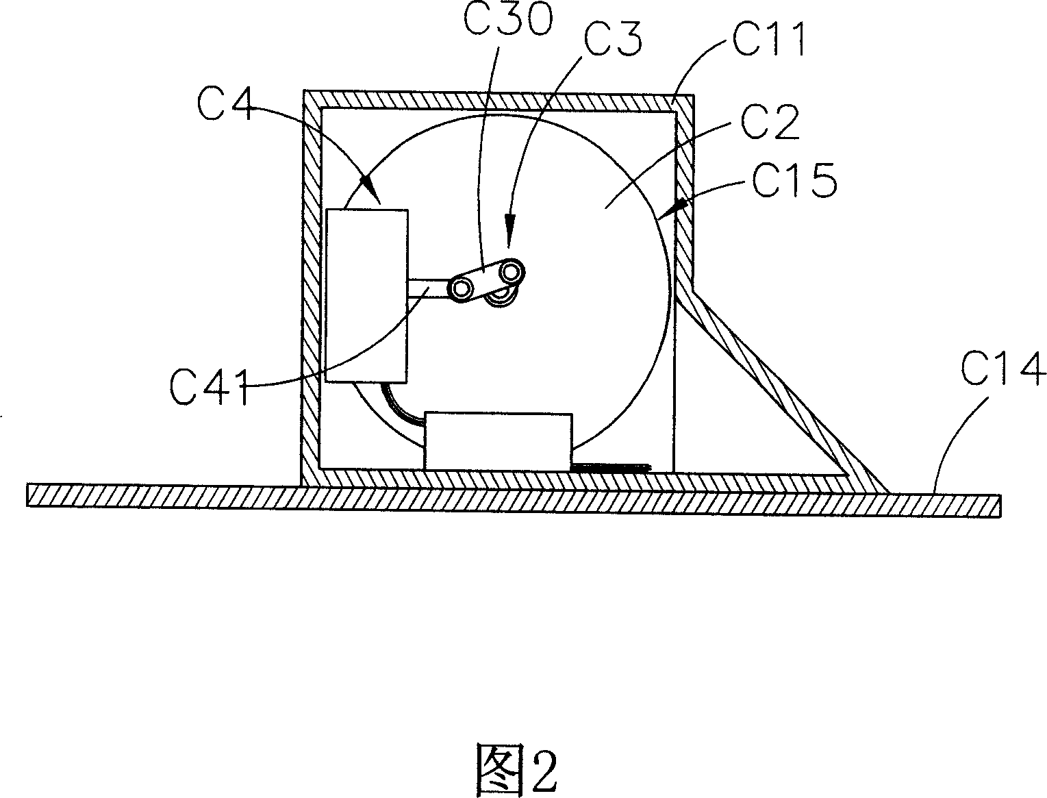
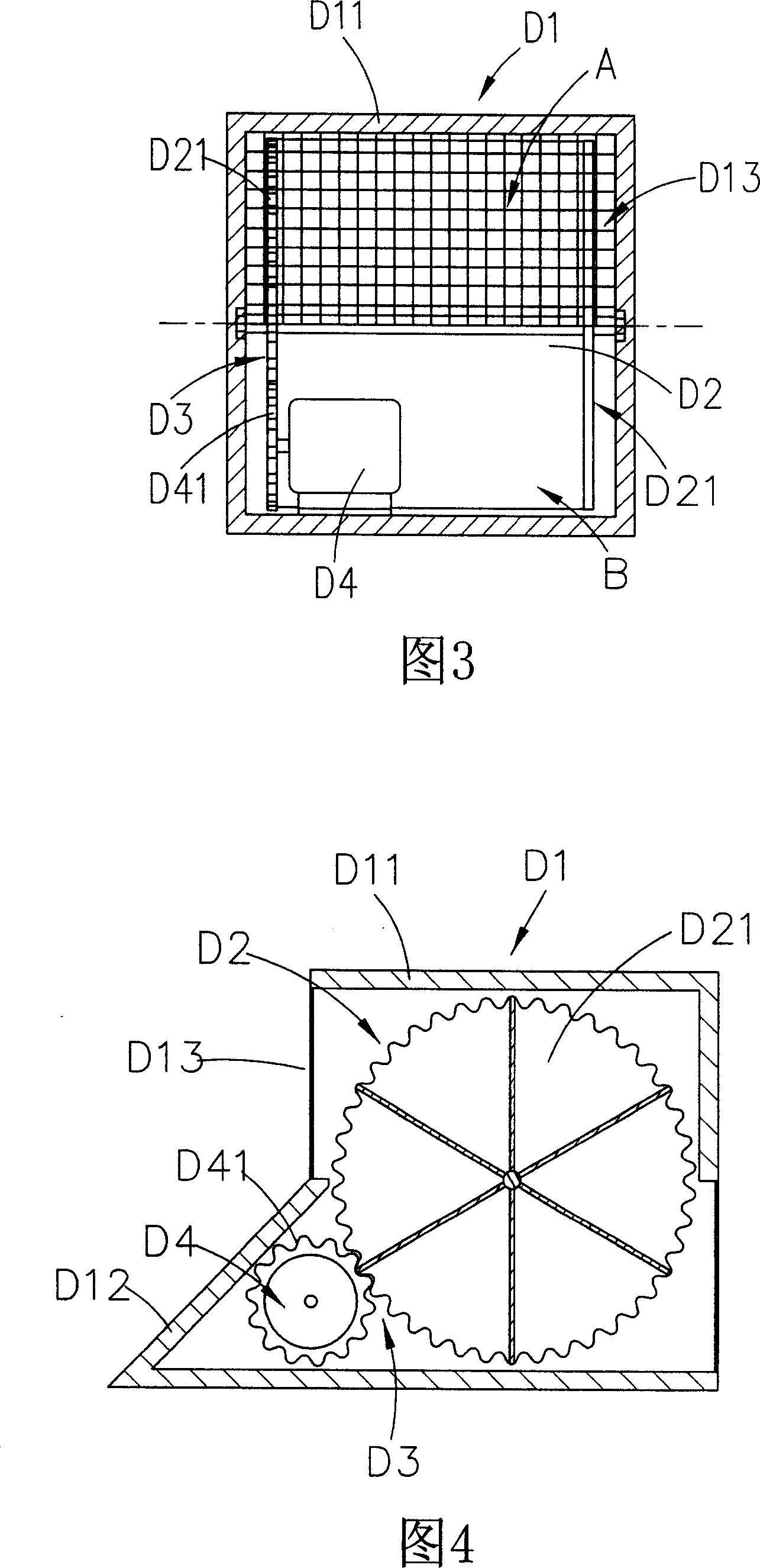
[0018] However, in this wind power generation device D1, the components such as the rotary generator D4 and the transmission mechanism D3 are placed near the air inlet D13, which is not easy to be isolated from the pollutants entering the device to prevent these components from being invaded, especially in this wind power generation device D1. In order to be installed on the outer surface of the vehicle, the intrusion of rainwater, dust, etc. is inevitable. Without good isolation, these components will be easily polluted and damaged

Method used


Image

  • Wind power generation plant of delivery vehicle
  • Wind power generation plant of delivery vehicle
  • Wind power generation plant of delivery vehicle

Examples


Embodiment Construction

[0082] Please refer to FIG. 5 to FIG. 10 , which are the best embodiments selected by the present invention. Firstly, the wind power generating device of the present invention is installed on the outer surface of the vehicle, so that the wind force generated when the vehicle is moving can be used to drive the wind power generating device.

[0083] As shown in each figure, the wind power generation device of the present invention has a casing 1, which is installed on the outer surface 1A of the vehicle, and the casing 1 has an air inlet 11 and an air outlet 12, and the casing 1 corresponds to the air inlet 11. The tuyere 11 is provided with a streamline plate 2 to reduce the wind resistance on the windward side and guide the wind to the air inlet 11, and the air inlet 11 and the air outlet 12 are respectively provided with a shielding net 10 to prevent foreign objects from entering.

[0084] Please refer to Fig. 6 to Fig. 7, which are respectively an internal assembly diagram a...


PUM


Abstract

A wind power generator of the launch vehicle is a generation mechanism which is distributed and designed by the rotating wheel and the fixed flat plates. It drives the blade rotating by the wind power produced when the launch vehicle moving. It also drives the rotating wheel of the generation mechanism to make the magnetic-field component on the rotating wheel and the generation coil on the fixed flat plate move tangentially and make the magnetic flux changing to generate power. Without the moving transmission of the crank link, the generation mechanism with larger diameter can be designed to make full use of the space on the blade sides. The appearance of the generation mechanism is flat, the generation coil and the magnetic-field component have fast tangent speed, which can achieve the batter generation benefit.

Description

technical field [0001] The invention relates to a wind power generation device, especially a device on the outer surface of a vehicle, which does not need to be converted by a crank connecting rod transmission mechanism, and thus can obtain power generation benefits. Background technique [0002] Recently, due to the scarcity of petroleum resources, its price has become very expensive, and the greenhouse effect and other pollution problems caused by long-term use of petroleum fuels have become increasingly serious. Based on the above reasons, vehicles such as automobiles are developing towards electrification, such as electric vehicles, hybrid vehicles, etc., in order to reduce the use of petroleum fuels. [0003] Compared with the fossil fuels used in internal combustion engine vehicles, the electric energy storage capacity of batteries used in general electric vehicles is relatively small, and they can only travel a short distance on a single charge, and the battery chargi...

Claims


Application Information

Patent Timeline
Patent Type & Authority Applications(China)
IPC IPC(8): F03D9/00F03D3/04F03D9/25
CPCY02E10/74
Inventor 陈文庆谢武灯
Owner HIWIN TECH
Learn More