Permanent-magnetic electric machine rotor magnet steel fixing structure

A permanent magnet motor, fixed structure technology, applied in the direction of magnetic circuit shape/style/structure, magnetic circuit rotating parts, etc., can solve difficult second or even third dynamic balance test, fixed parts damage, poor craftsmanship, etc. problem, to achieve the effect of light weight, reduced machining accuracy and low machining cost

Active Publication Date: 2007-12-05
BYD CO LTD
View PDF0 Cites 23 Cited by
  • Summary
  • Abstract
  • Description
  • Claims
  • Application Information

AI Technical Summary

Problems solved by technology

[0004] The magnet fixing structure alone has five components with relatively complex structures. During the assembly process, welding or tight fitting is even required, and the workmanship is poor; and the key is to do the dynamic balance test of the rotor. After completing a dynamic balance, various fixing parts Has been damaged, it is impossible or difficult to carry out the second or even third dynamic balance test

Method used


Image

  • Permanent-magnetic electric machine rotor magnet steel fixing structure
  • Permanent-magnetic electric machine rotor magnet steel fixing structure

Examples


Embodiment Construction

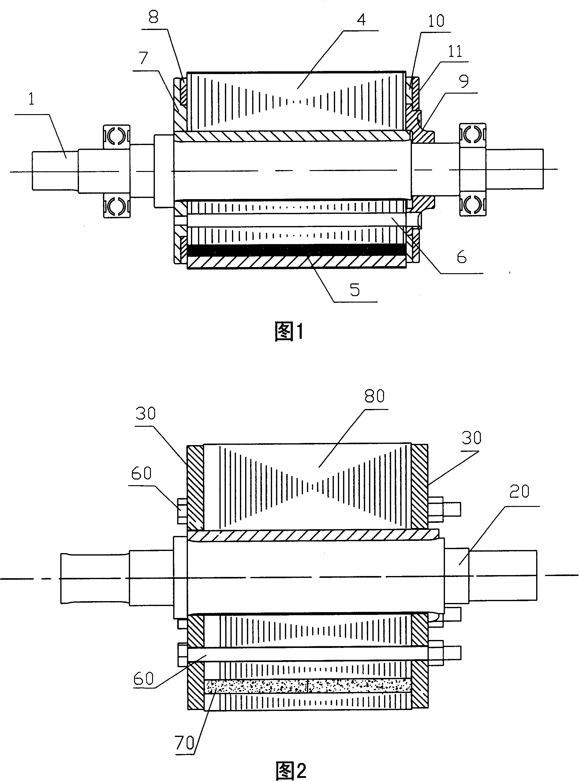
[0018] Please refer to FIG. 2 and FIG. 3 , the permanent magnet motor rotor magnetic steel fixing structure of the present invention is mainly composed of a rotating shaft 20 , a rotor core 80 , two magnetic steel pressure plates 30 , magnets 70 , and bolts 60 .

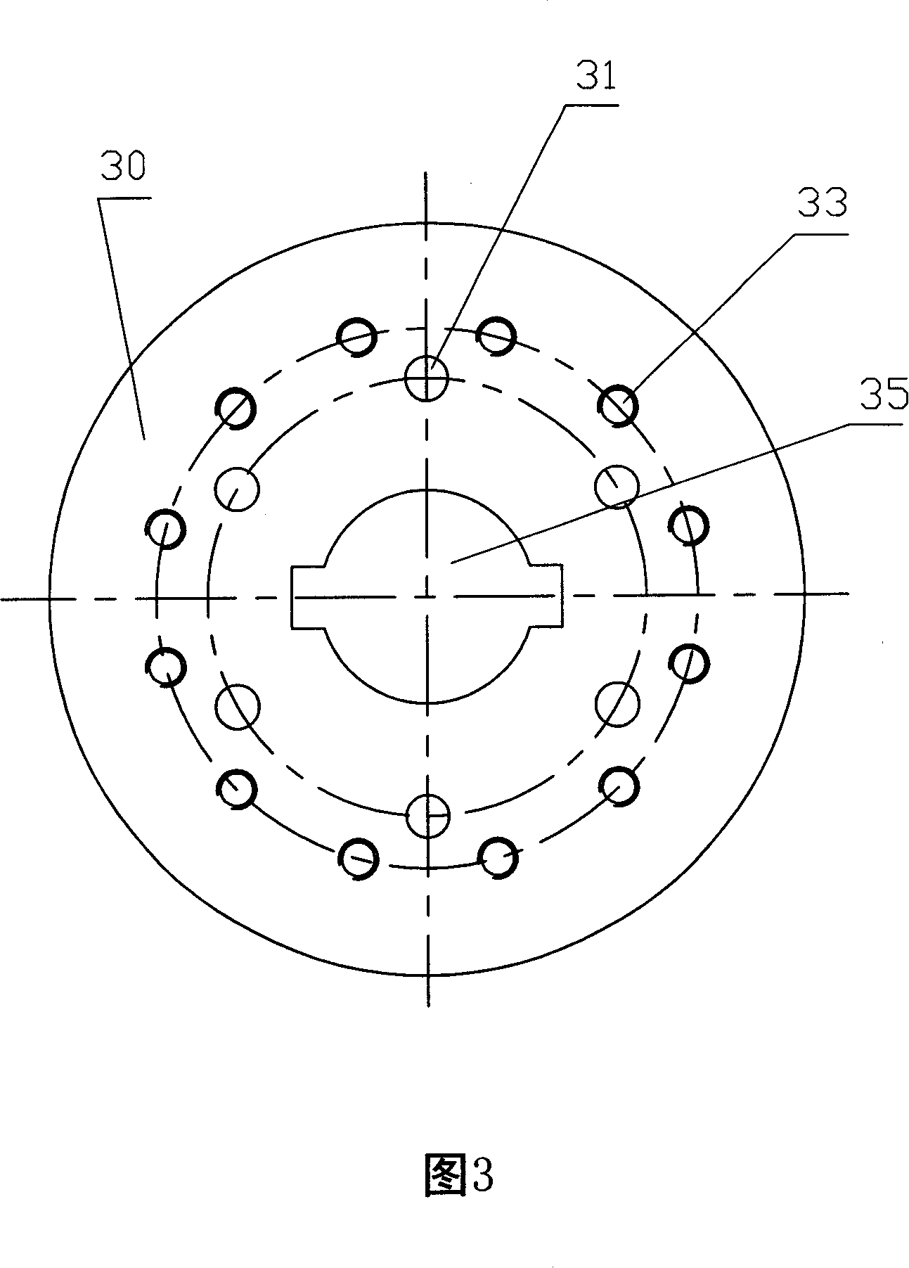
[0019] The two magnetic steel pressure plates 30 are respectively arranged on the two end surfaces of the rotor core 80. Since the length of the magnet 70 is consistent with the length of the rotor core 80, the magnetic steel pressure plates 30 are directly in contact with the two end surfaces of the rotor core 80 to form a rotor. Several magnetic steel sheets of the iron core 80 are superimposed on the axial direction of the rotating shaft 20, wherein each magnetic steel sheet is correspondingly provided with a locking hole (not shown), and the two magnetic steel pressing plates 30 are The position corresponding to the locking hole is provided with a through hole 31, and then the bolt 60 is passed through the locking...


PUM


Abstract

The invention discloses a permanent motor rotor alnico fixing structure, mainly comprising: rotating shaft, rotor iron core, two alnico pressure plates and magnet, where the two alnico pressure plates are separately arranged on two end surfaces of the rotor iron core and fixed, the rotating shaft runs through the middles of the alnico pressure plates and the rotor iron core and is fixed, and especially, the alnico pressure plate is formed with several screw holes for regulating dynamic balance, where the axes of these screw holes are distributed on a circle coaxial with the rotating shaft. And it has simple structure and is convenient to dynamic balancing.

Description

technical field [0001] The invention relates to a permanent magnet motor rotor magnetic steel fixing structure, in particular to a permanent magnet motor rotor magnetic steel fixing structure with simple structure and convenient dynamic balance counterweight. Background technique [0002] At present, a general embedded permanent magnet brushless DC motor is composed of four parts: a stator assembly, a rotor assembly, a casing assembly, and a Hall assembly. The stator assembly includes a stator core with a slot and coil windings placed in the slot; the rotor assembly includes a rotor core with a magnet hole, a permanent magnet placed in the hole, a shaft and a magnetic steel plate, because the rotor involves When it comes to the dynamic balance test and it is necessary to fix the permanent magnets in the rotor core, the common practice is to fix the core and the shaft together with various complex steel material fixing structures, the rotor is too heavy and the repeatability ...

Claims


Application Information

Patent Timeline
Patent Type & Authority Applications(China)
IPC IPC(8): H02K1/28
Inventor 齐文明
Owner BYD CO LTD
Why Eureka
Try Eureka