Additional drive system by diverting a fluid flow

A driving device, a technology for additional driving, which is applied in the directions of wind turbines, motors, transportation and packaging at right angles to the wind direction, and can solve problems such as transportation tools that cannot be used in relatively fast movements.

Inactive Publication Date: 2007-12-12
沃尔夫冈・约布曼有限责任公司
View PDF4 Cites 7 Cited by
  • Summary
  • Abstract
  • Description
  • Claims
  • Application Information

AI Technical Summary

Problems solved by technology

[0005] The disadvantage of this additional drive is that it can only be driven in a defined wind direction (up to two compass (strich) in the direction of travel
[0006] For this reason, this known additiona

Method used


Image

  • Additional drive system by diverting a fluid flow
  • Additional drive system by diverting a fluid flow
  • Additional drive system by diverting a fluid flow

Examples


Embodiment Construction

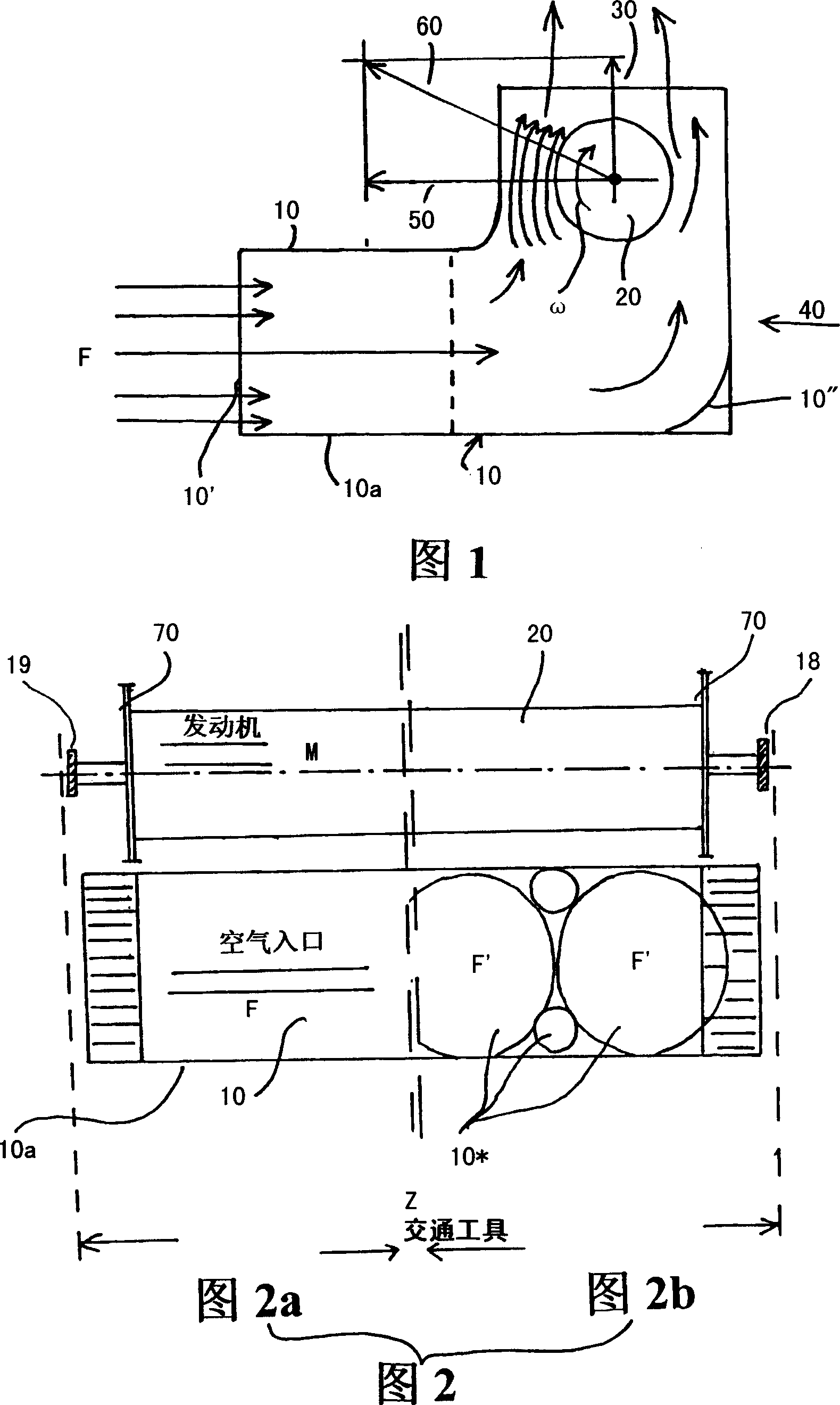
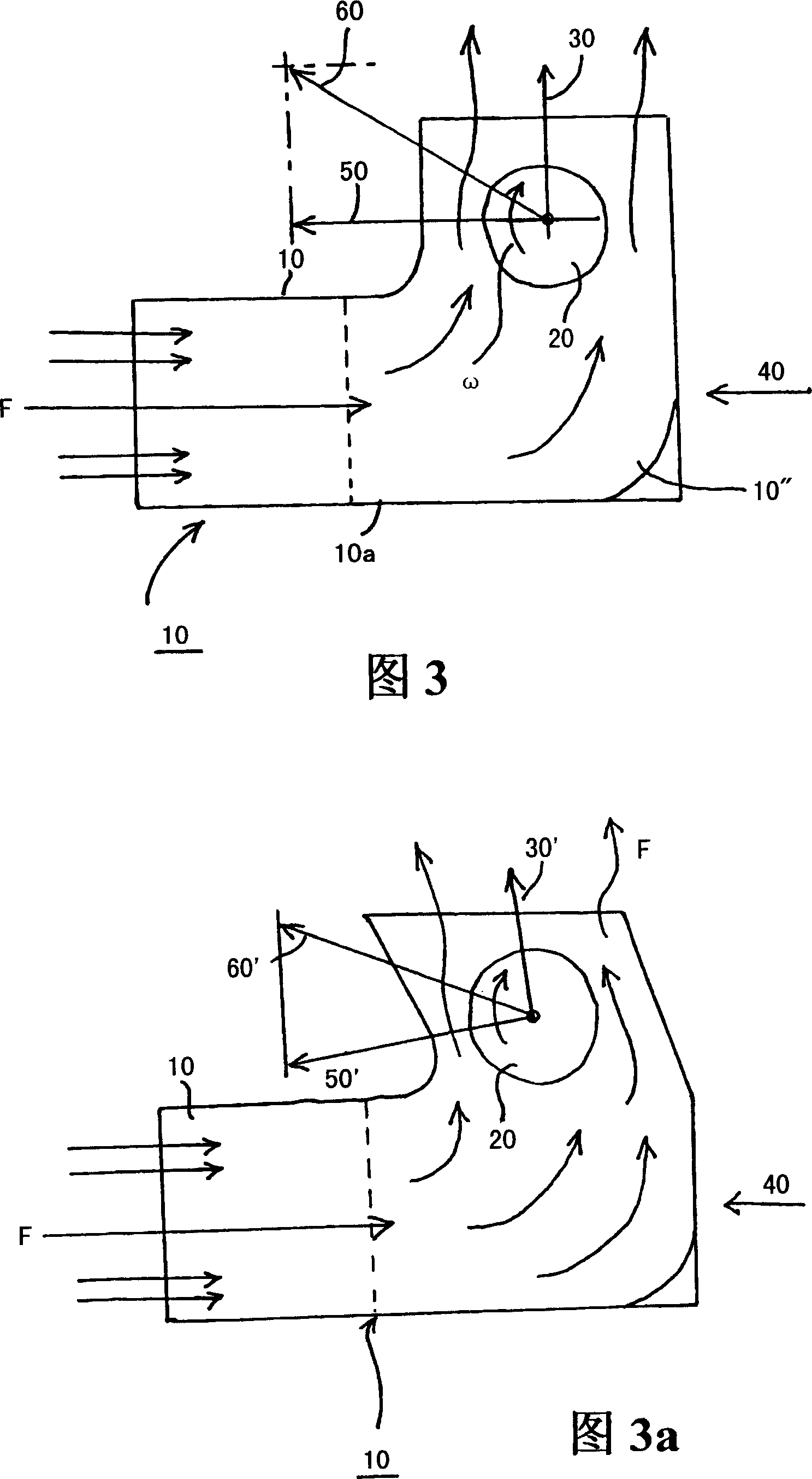
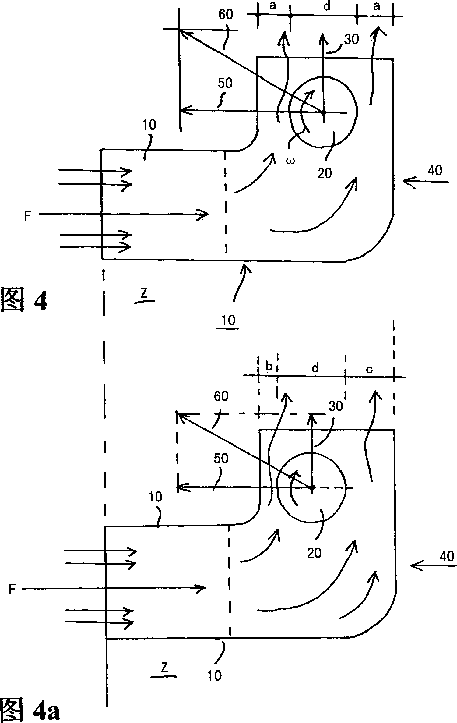
[0022] FIG. 1 shows a first embodiment in which the travel wind F enters the channel 10 and is deflected upwards before hitting a horizontally arranged rotating cylinder 20 . This produces a first force 30 and a second force 40 acting on the channel 10 . But the driving force or lateral driving force produced by the rotating cylinder is 50 times greater and a "synthetic force" 60 is generated as the propulsion force. This force is transmitted to the vehicle Z (not shown) (shown below the channel 10 in FIG. 2 ). Here too, a main forward drive (not shown in further detail), such as a motor driving the wheels via a transmission, is provided.

[0023] As shown in FIG. 1, the traveling wind entering the channel 10 enters an inlet 10', is then directed through a section of the channel and is turned upward at a turning point 10" so as to pass to a rotating cylinder 20 located in a higher section. The rotational velocity and direction ω of the cylinder are marked such that the corre...


PUM


Abstract

The invention relates to the use of a drive system working on the basis of the Magnus Effect which is used to provide a drive mechanism in addition to an existing drive device. The aim of the invention is to produce a drive directly in front of the front impacting fluid flow. The invention also relates to the use of a drive system for a relatively fast moving vehicle by means of a first drive system, said drive system comprising a rotating, horizontally arranged cylinder (20) provided with end disks (70) as an additional drive. A fluid flow (F), which is produced by the first drive system, enters into a channel (10) and is diverted (10'') in the direction thereof in said channel whereupon it impinges upon the rotating cylinder (20). The complimentary drive is produced in a desired direction based on the Magnus Effect.

Description

technical field [0001] The invention relates to the use of a drive operating on the basis of the Magnus effect for the purpose of an additional drive to an existing drive. Background technique [0002] A wind-powered additional drive has been disclosed, based on the Magnus effect (Magnus, 1852), for which it exploits other physical foundations (Prantl. 1904) and used in the development of the Flettner rotor (Flettner, 1922). The "Flettner rotor" for ship power plants got its first realization, see GB-A2 102755 (Blohm & Voss). [0003] The "Flettner rotor" was obtained on the basis of the experiments of AVA, Göttingen (1922-1924) and by Germania-Werft on the refitting of sailing boats "Buckau" (1924) and RMS "Barbara" (1926). [0004] In these wind-additional drives, the wind and travel wind blow directly onto the driven rotating cylinder (rotor), which, through the Magnus effect, produces a not insignificant driving force. [0005] The disadvantage of this additional drive...

Claims


Application Information

Patent Timeline
IPC IPC(8): B63H9/02F03D3/00
CPCY02T70/58B63H9/02Y02T70/5236
Inventor 沃尔夫冈·约布曼彼得·施塔默
Owner 沃尔夫冈・约布曼有限责任公司
Why Eureka
Try Eureka