
Induction type synchronous motor

A synchronous motor and armature technology, applied in synchronous machines, electromechanical devices, electrical components, etc., can solve the problems of complex structure, unstable power supply, and reduced life, and achieve simplified structure, high power output, and extended life. Effect

Inactive Publication Date: 2007-12-12
SUMITOMO ELECTRIC IND LTD
View PDF1 Cites 8 Cited by
  • Summary
  • Abstract
  • Description
  • Claims
  • Application Information

AI Technical Summary

Problems solved by technology

Therefore, the structure becomes complex
In addition, there are problems such as a decrease in life due to contact wear at the slip ring 9, and instability of power supply due to instability of the sliding contact at the slip ring 9

Method used


Image

  • Induction type synchronous motor
  • Induction type synchronous motor
  • Induction type synchronous motor

Examples


Embodiment Construction

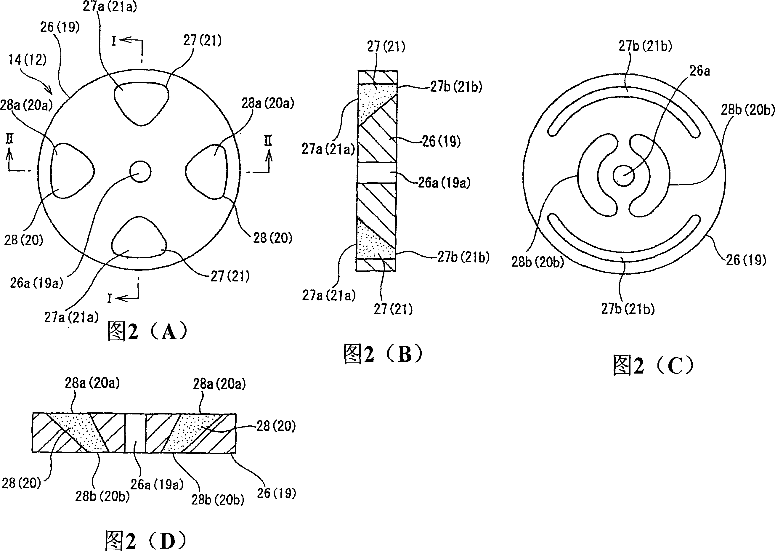
[0072] Embodiments of the present invention will be described with reference to the drawings.

[0073] FIG. 1 shows an induction-type synchronous motor (induction-type synchronous motor) 10 according to a first embodiment.

[0074] The induction type synchronous motor 10 has an axial air gap structure in which the rotating shaft 34 penetrates the field stator 11 , the rotor 12 , the armature stator 13 , the rotor 14 , and the field stator 15 in sequence. The field stators 11, 15 and the armature stator 13 are fixed to the mounting surface G with an air gap provided with respect to the rotation shaft 34, and the rotors 12, 14 are assembled and fixed by providing an air gap from the rotation shaft 34 to the rotors 12, 14 to the axis of rotation 34 .

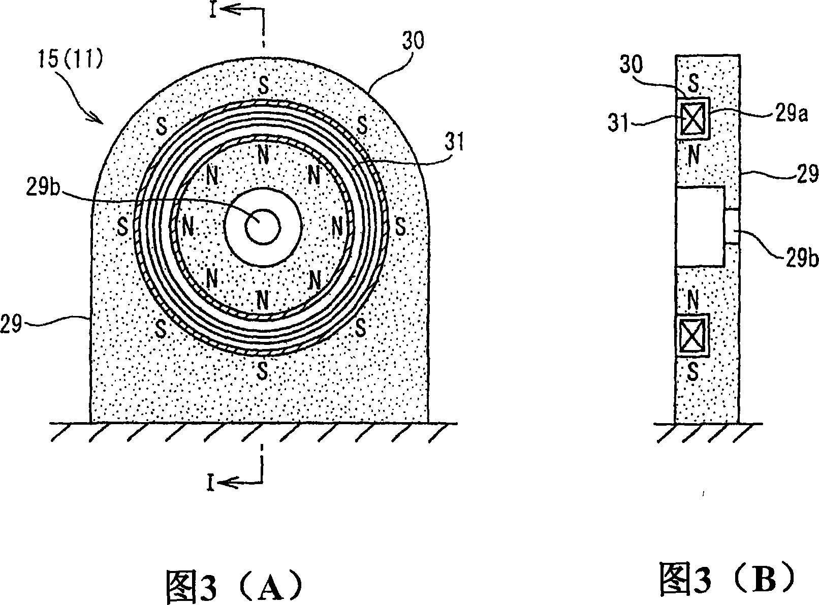
[0075] The field stator 11 and the field stator 15 are bidirectionally symmetrical with respect to the image. Therefore, one of the stators 15 is schematically shown in FIGS. 3(A) and 3(B).

[0076] Each field stator 11 , 15 has...


PUM


Abstract

An inductor type synchronizer includes: field side stators (11, 15) having field coils (18, 31) where an N pole and an S pole are formed concentrically; rotors (12, 14) having N pole inductors (20, 28) arranged to oppose to the N pole of the field coils (18, 31) and S pole inductors (21, 27) arranged to oppose to the S pole of the field coils (18, 31), and having a fixed rotation axis (34); and an armature side stator (13) having an armature coil (24) arranged to oppose to the N pole inductors (20, 28) and the S pole inductors (21, 27).

Description

technical field [0001] The invention relates to an induction synchronous motor. More specifically, the present invention relates to a motor or generator comprising a magnetic material (inductor) that induces a magnetic flux to a predetermined position on the field side, the rotation of the rotary shaft being synchronized with the polarity change of the armature . Background technique [0002] As shown in FIG. 20, in the generator disclosed in JP-A-54-116610 or JP-A-6-86517, the rotating shaft 1 penetrates through a bearing 2 through a bracket 2, which serves as a housing. The field winding 5 is arranged on the periphery of the yoke 4, which is assembled and fixed to the rotary shaft 1, and the claw-shaped magnetic poles 6 and 7 are arranged so as to protrude from the left and right sides of the field winding 5 alternately, whereby the rotor formed into a whole. Meanwhile, the stator winding 8 is arranged on the bracket 2 so as to face the claw poles 6 and 7 . Electric po...

Claims


Application Information

Patent Timeline
Patent Type & Authority Applications(China)
IPC IPC(8): H02K21/38H02K16/00
CPCH02K19/103H02K21/42H02K55/02Y02E40/622Y02E40/60H02K1/27
Inventor 冈崎彻大桥绅悟杉本英彦竹田敏雄
Owner SUMITOMO ELECTRIC IND LTD
Learn More