Manufacturing method for adhesive assembly inductance on micro heavy current meter surface

A manufacturing method and high-current technology, applied in coil manufacturing, etc., can solve the problems of mass production that cannot be matched with automation equipment and high labor costs, and achieve good yield reliability, shorten delivery time, and increase the number of turns that can be wound.

Inactive Publication Date: 2007-12-19
TAI TECH ADVANCED ELECTRONICS CO LTD
View PDF0 Cites 3 Cited by
  • Summary
  • Abstract
  • Description
  • Claims
  • Application Information

AI Technical Summary

Problems solved by technology

[0006] 3. The labor cost is too high to be mass-produced with automation equipment

Method used


Image

  • Manufacturing method for adhesive assembly inductance on micro heavy current meter surface
  • Manufacturing method for adhesive assembly inductance on micro heavy current meter surface
  • Manufacturing method for adhesive assembly inductance on micro heavy current meter surface

Examples


Embodiment Construction

[0030] In order to make it easy for your examiner to understand the other features and advantages of the utility model and the effects achieved, the utility model is hereby combined with the accompanying drawings, and the details are as follows:

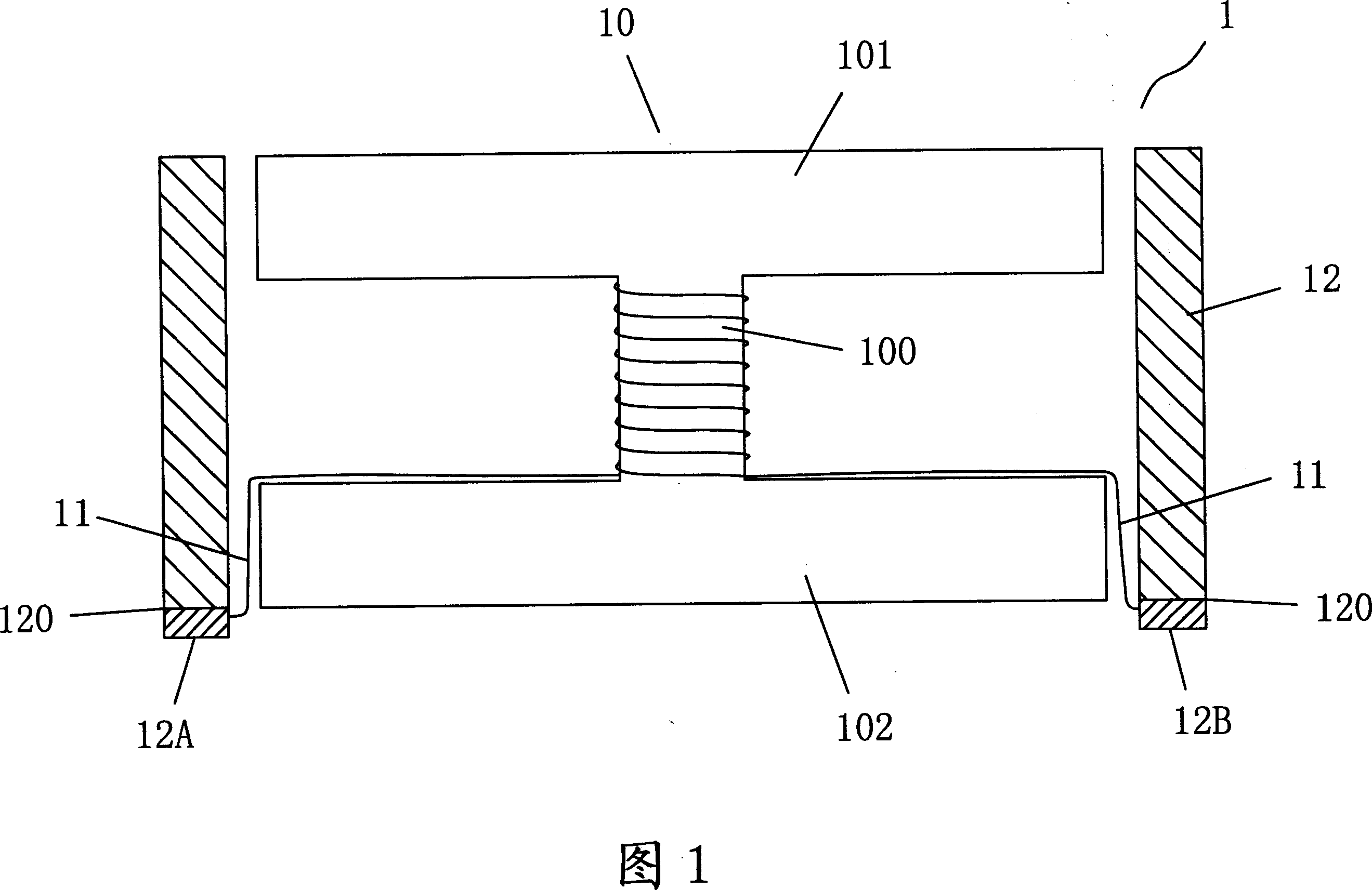
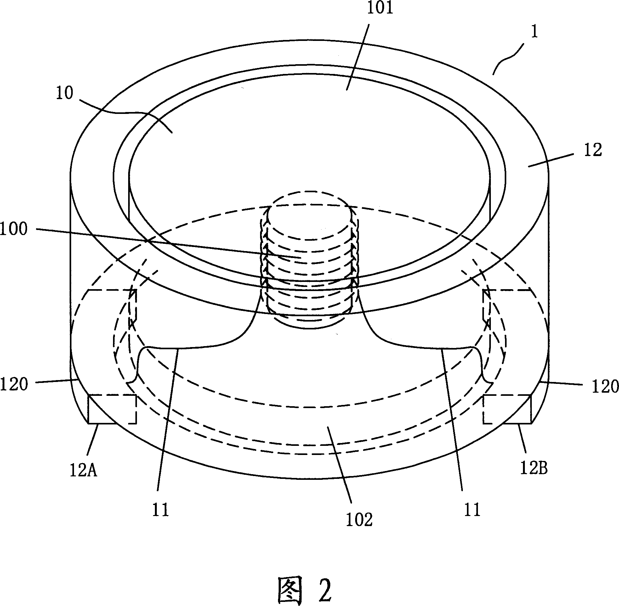
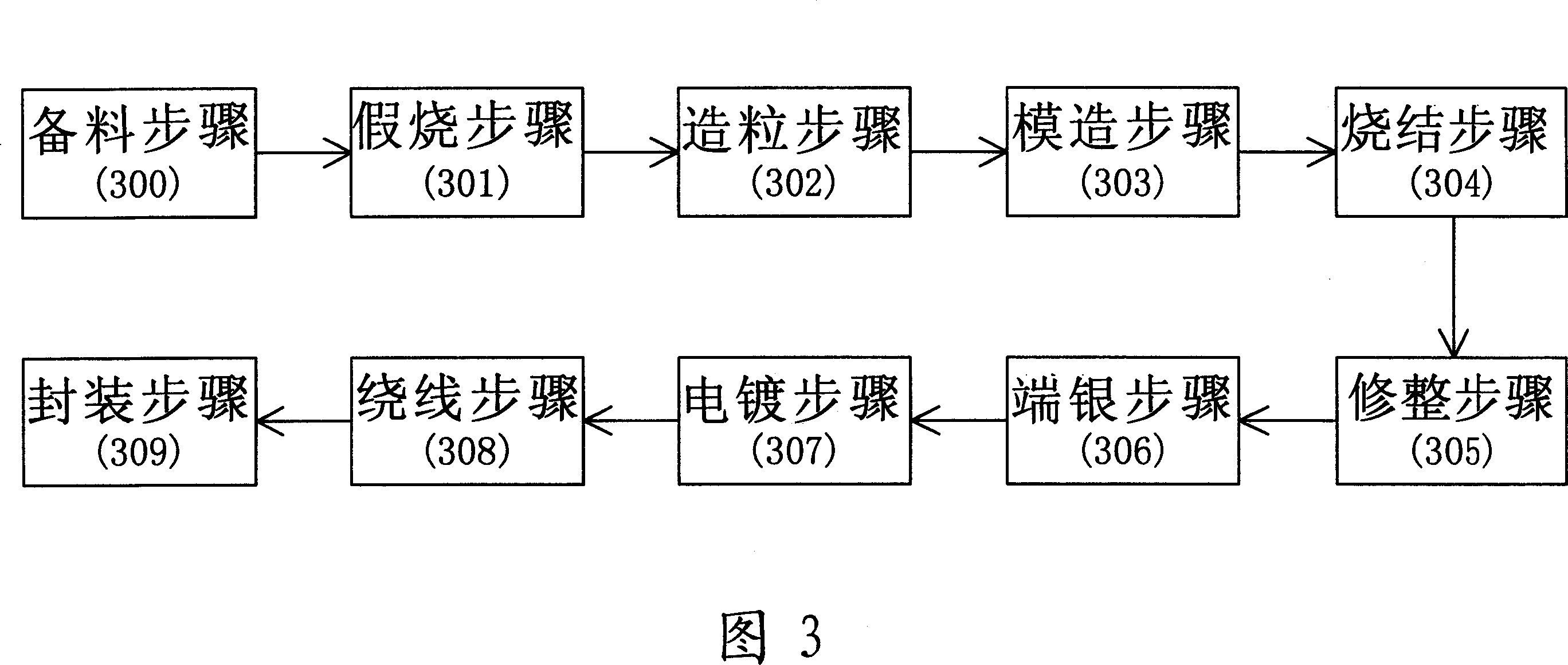
[0031] Please refer to Fig. 3 and Fig. 4, according to the present invention, a method for manufacturing a miniaturized high-current surface mount component inductor 4 is provided, and the present invention includes the following steps:

[0032] Material preparation step 300: Prepare the raw material powder with the required specification and size, and the powder can be a ferrite magnet (Ferrite) or a ceramic magnet (Ceramic);

[0033] False firing step 301: Mix the powder in the preparation step with a vibrator evenly, pour the powder into a sagger, and put it into a high-temperature tunnel furnace, keep the temperature at 850-950°C and heat for about 2 to 3 hours, and naturally cool after burning out, the main purpose of which is t...


PUM

PropertyMeasurementUnit
particle diameteraaaaaaaaaa

Abstract

This invention provides a manufacturing method for micro large current surface-adhered inductors including: 1, stocking: preparing material powder of required specifications, 2, artificial burning: eliminating impurities of the powder to crystallize the powder initially, 3, sizing: adding resin and dispersant to it to make it to a material with necessary grain size, 4, molding: punching the material to mold by a molding machine, 5, sintering: crystallizing it in a high temperature furnace, 6, finishing: eliminating raw edges on the surface, 7, ablating an Ag powder layer on one side surface, 8, plating: plating it to a welded part, 9, winding: binding the wires on a central post of the iron core by an automatic winding machine, 10 packaging it to finish the product.

Description

technical field [0001] The invention relates to a method for manufacturing inductors, in particular to a method for manufacturing inductors of miniaturized high-current surface mount components. Background technique [0002] The existing surface mount device (SMD) inductance structure used in miniaturization and high current is shown in FIG. , the iron core 10 is in the shape of an I-shape, the center column 100 of the iron core 10 is vertically wound and stacked by the wire group 11 for at least one turn, and the two ends of the wire group 11 are respectively extended and welded. At the welded portions 12A, 12B on one side 120 of the ring cover 12, the ring cover 12 covers the iron core 10 to form an SMD inductance 1 part, and pass through the one side 120 of the ring cover 12 The soldering portions 12A, 12B of the circuit board (not shown in the figure) are connected to each other. When manufacturing an inductance part using surface mount technology (SMT), the total heig...

Claims


Application Information

Patent Timeline
Patent Type & Authority Applications(China)
IPC IPC(8): H01F41/04
Inventor 谢明谚
Owner TAI TECH ADVANCED ELECTRONICS CO LTD
Why Eureka
Try Eureka