Bi motor method for controlling unmanned helicopter

An unmanned helicopter, dual-engine technology, applied in the direction of engine control, machine/engine, joint control, etc., can solve the problem of not being able to effectively balance the output torque rotor speed at the same time, achieve simple structure, increase service life, and increase output torque Effect

Inactive Publication Date: 2007-12-26
NANJING UNIV OF AERONAUTICS & ASTRONAUTICS
View PDF0 Cites 9 Cited by
  • Summary
  • Abstract
  • Description
  • Claims
  • Application Information

AI Technical Summary

Problems solved by technology

[0003] In order to overcome the shortcomings that the existing unmanned helicopter dual-engine control adopts a single closed-loop control mode of engine speed or torque, which cannot effectively balance the output torq

Method used


Image

  • Bi motor method for controlling unmanned helicopter

Examples


Embodiment Construction

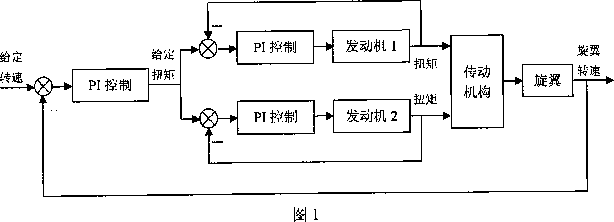
[0007] The specific embodiment of the present invention is shown in Figure 1, engine 1 and engine 2 respectively utilize the torque sensor to measure the inner loop of closed loop, inner loop adopts PI control method, the given torque of the inner loop of two engines is connected in parallel Together, it can ensure that the output torque of the two engines can be kept consistent at any time. The output torque of the two engines drives the rotor to rotate through the transmission mechanism, and the rotor speed is used to form an outer loop. The outer loop adopts the PI control method, and the outer loop control The output of the inverter is used as the given torque of the two parallel inner loops to realize the control of the rotor speed of the unmanned helicopter.


PUM


Abstract

The invention relates to unmanned helicopter bi-motor controlling method. It utilizes each motor torque detector to measure output torque to form loop locked inner looping of which given torsion moments are connected in parallel. The output torque is used to drive rotary wing of which rotating speed can be formed the outer looping. The outer looping controller output can be used as parallel inner looping given torsion moment to realize speed control for unmanned helicopter. Thus the invention can effectively balance the bi-motor output torque and increase rotor speed smoothness at the same time.

Description

1. Technical field [0001] The invention relates to a control method for two engines of an unmanned helicopter, which can effectively balance the output torques of the two engines and improve the stability of the rotation speed of the rotor. 2. Background technology [0002] At present, the dual-engine control of unmanned helicopters generally adopts a single closed-loop control of engine speed or torque. On the one hand, for the single closed-loop control of engine speed, due to the difference in the input and output characteristics of the two engines, it is difficult to balance the output of the two engines. torque, it is easy to cause a large difference in the service life of the two engines; on the other hand, due to changes in the engine load, the speed deviates from the expected value, and it is difficult to improve the stability of the engine speed by only using a single closed-loop control of the torque. This single control method cannot simultaneously effectively bal...

Claims


Application Information

Patent Timeline
IPC IPC(8): B64C19/02F02D25/00G05B19/418
CPCY02P90/02
Inventor 盛守照王道波
Owner NANJING UNIV OF AERONAUTICS & ASTRONAUTICS
Why Eureka
Try Eureka