Axial flow cooling blower fan

A cooling fan, axial-flow technology, applied in axial-flow pumps, mechanical equipment, non-variable pumps, etc., can solve the problems of power plant safety production and operation, affecting the cooling effect of air-cooled condensers, economic losses, etc. To achieve the effect of improving the heat dissipation effect, improving the heat dissipation effect, and enhancing the convective heat transfer capacity

Inactive Publication Date: 2007-12-26
BEIHANG UNIV
View PDF0 Cites 8 Cited by
  • Summary
  • Abstract
  • Description
  • Claims
  • Application Information

AI Technical Summary

Problems solved by technology

However, in the hot summer season, the ambient temperature is very high, especially when the natural wind blows from the side of the boiler room and forms heat backflow under the air cooling tower, the air volume blown by the existing fan cannot meet the actual high temperature condition of the air-coole

Method used


Image

  • Axial flow cooling blower fan
  • Axial flow cooling blower fan
  • Axial flow cooling blower fan

Examples


Embodiment Construction

[0025] The present invention will be further described in detail below in conjunction with the accompanying drawings.

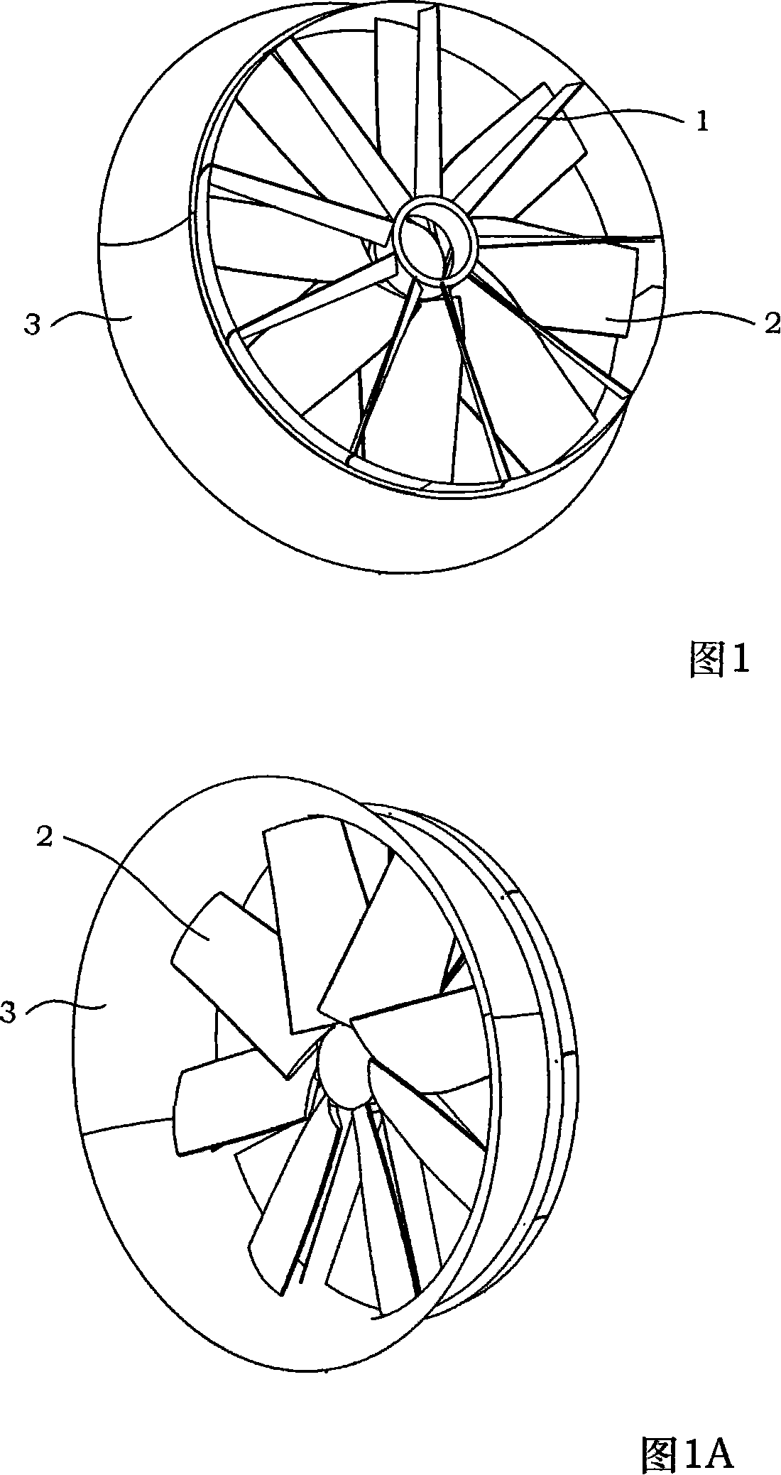
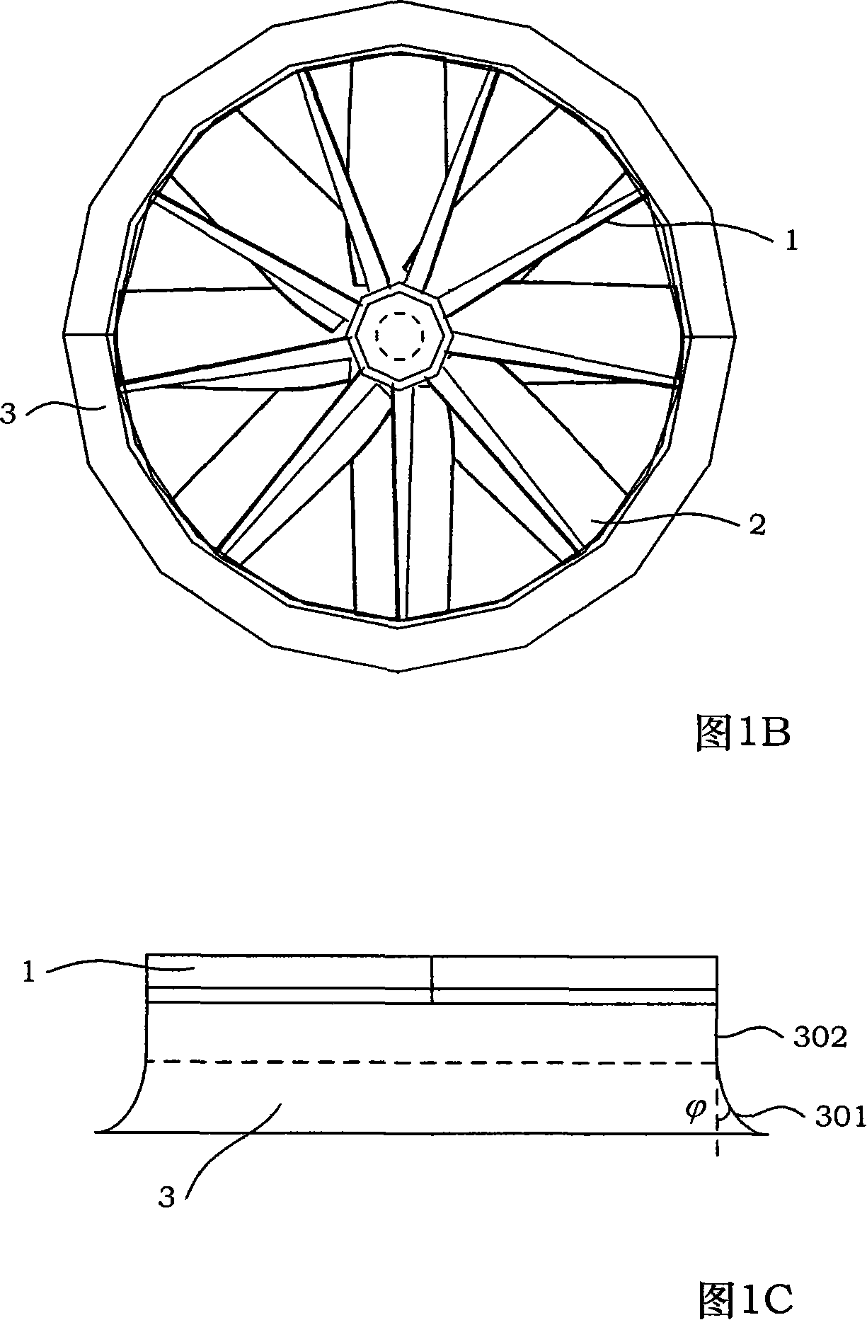
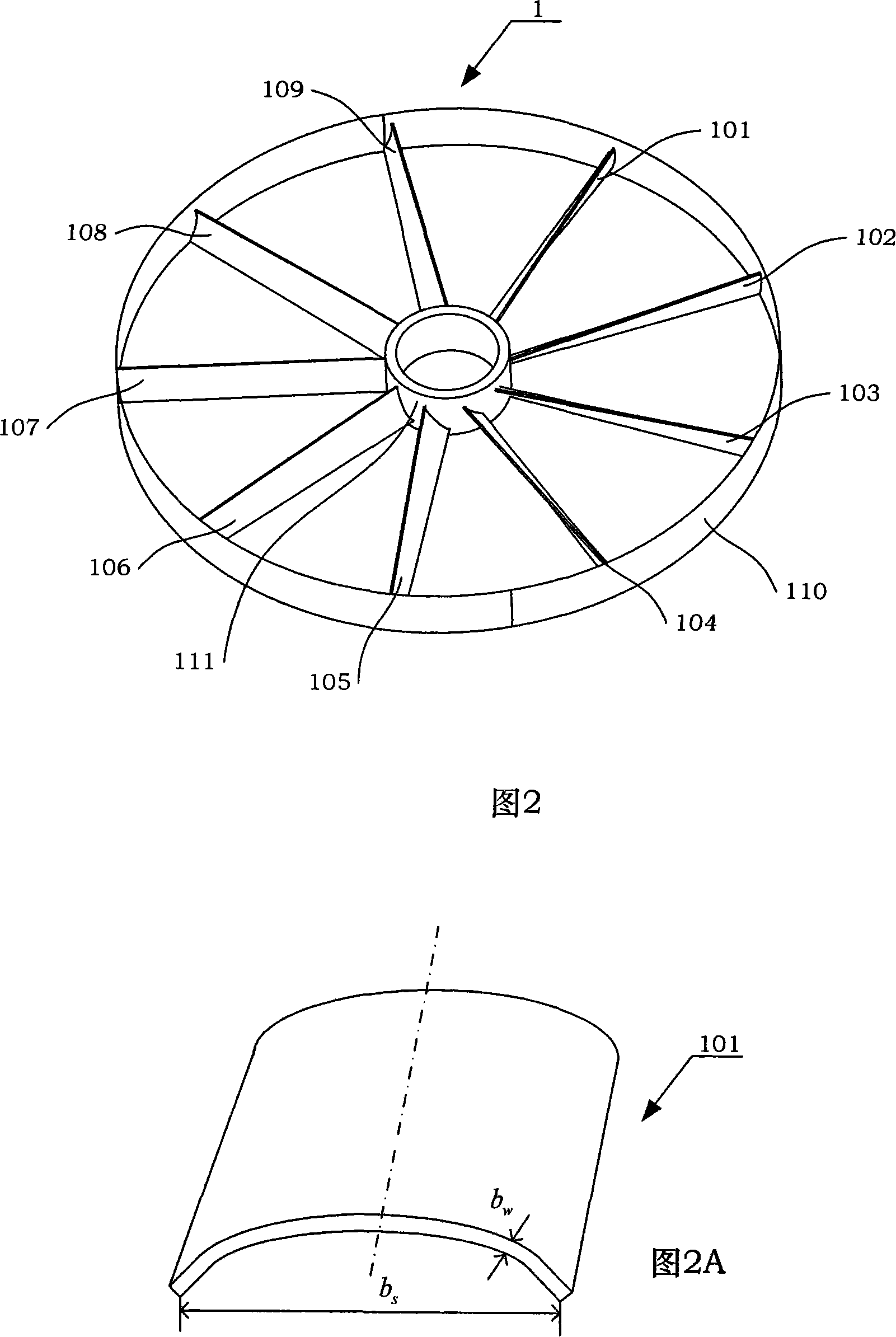
[0026] The present invention is a large diameter 8 ~ 10m, low pressure head 70 ~ 130Pa, high air volume 440 ~ 550m 3 The / s axial flow cooling fan is composed of a motor (not shown in the figure), an air coil 3, a deflector assembly 1 and a paddle assembly 2 (see Fig. 1, Fig. 1A, Fig. 1B), and the deflector The outer ring 110 of the vane assembly 1 is connected to the smooth section 302 of the wind ring 3, the blade assembly 2 is assembled in the wind ring 3, and the output shaft of the motor passes through the inner ring 111 of the deflector assembly 1 and the blade assembly 2 The hub 209 is connected. (See FIG. 1C ) The shape of the wind ring 3 is provided with a smooth section 302 and an expansion section 301 from top to bottom, and the expansion degree  at the end of the expansion section 301 is 3-10 degrees. In the present invention, when the motor dr...


PUM

PropertyMeasurementUnit
Okaaaaaaaaaa

Abstract

This invention discloses an axial cooling blower with large diameter of 8-10m, low pressure head of 70-130Pa and high blast volume of 440-550m3/s composed of a motor, a bustle pipe, a deflector vane component and a blade component, in which the outer circle of the deflector vane component is connected with one end of the bustle pipe, the vane component is assembled in the pipe, the output shaft of the motor passes through the inner circle of the deflector vane and connects to the rim of the vane, which applies a theory of free vortex blade lattice, applies low Renault number and high lift aerofoil and increases torsion angle of the vane to increase chord length of the tine to manufacture a new type of blower and installs a deflector vane to recover rotation energy of the outlet and increase hydrostatic lifting of the blower so as to increase speed of the output of an air cooler.

Description

technical field [0001] The invention relates to an axial flow cooling fan, which has a large diameter of 8-10m, a low-pressure head of 70-130Pa, and a high air volume of 440-550m 3 / s. Background technique [0002] Since large axial flow fans play an important role in forced convection heat transfer in direct air cooling systems of thermal power plants, the performance of the fans directly determines the cooling effect of the air-cooled condenser. Since the air-cooled condenser requires a large air volume during the heat dissipation process, but the pressure head is not large, the fan of the air-cooling system often adopts an axial flow fan with a low head, large air volume, and low noise. However, in the hot summer season, the ambient temperature is very high, especially when the natural wind blows from the side of the boiler room and forms heat backflow under the air cooling tower, the air volume blown by the existing fan cannot meet the actual high temperature condition ...

Claims


Application Information

Patent Timeline
IPC IPC(8): F04D19/00F04D29/54F04D29/38
Inventor 刘沛清赵万里屈秋林乔万鑫段会申
Owner BEIHANG UNIV
Why Eureka
Try Eureka