Homogeneous current circuit

A circuit and current sharing technology, applied in the direction of instruments, static indicators, etc., can solve the problems of multi-time adjustment and correction, and achieve the effect of strengthening the current sharing effect.

Inactive Publication Date: 2007-12-26
DELTA ELECTRONICS INC
View PDF0 Cites 1 Cited by
  • Summary
  • Abstract
  • Description
  • Claims
  • Application Information

AI Technical Summary

Problems solved by technology

However, when the number of lamp tubes increases, more adjustment capacitors 14 are required in the driving system 1", and each adjustment capacitor 14 and each balance transformer 19 also require more time for adjustment and calibration.

Method used


Image

  • Homogeneous current circuit
  • Homogeneous current circuit
  • Homogeneous current circuit

Examples


Embodiment Construction

[0031] A current sharing circuit according to a preferred embodiment of the present invention will be described below with reference to related drawings.

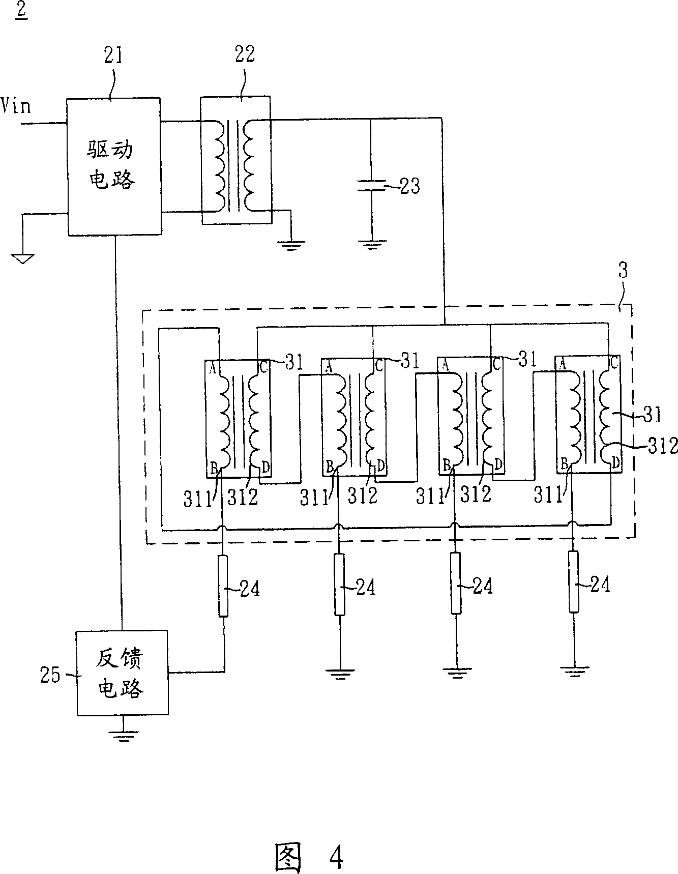
[0032] As shown in FIG. 4, a current sharing circuit 3 according to a preferred embodiment of the present invention is applied to a driving system 2, which can be applied to a backlight module and includes a driving circuit 21 and at least one main transformer 22. , at least one voltage stabilizing capacitor 23 , the current equalizing circuit 3 , a plurality of lamp tubes 24 and a feedback circuit 25 . A power supply Vin is input to the driving circuit 21, its voltage level is converted by the main transformer 22, and after the voltage is stabilized by the voltage stabilizing capacitor 23, the current equalizing circuit 3 receives the stable voltage to drive the plurality of lamp tubes 24 in a balanced manner. The current equalizing circuit 3 is electrically connected to the power supply Vin through the driving circuit 21 ...


PUM


Abstract

A current equalized circuit is prepared for electric-connecting each first balance transformer separately to each lamp tube and series-connecting multiple first balance transformer in sequence.

Description

technical field [0001] The present invention relates to a current equalizing circuit, in particular to a current equalizing circuit of a lamp tube. Background technique [0002] In recent years, the application of flat panel displays has become more and more popular, among which liquid crystal displays (Liquid Crystal Display, LCD) are the mainstream in the market. With the technological development of liquid crystal displays, in order to meet the demand for large-scale practical use, the number of Cold Cathode Fluorescent Lamps (CCFL) used as backlights must be increased to provide sufficient brightness. For example, if the number of liquid crystal displays increases to 40, the number of lamp tubes required may increase to more than 30. However, when the number of lamp tubes increases, the brightness among the lamp tubes tends to be uneven. The known technology solves this problem by impedance matching or adding a balance transformer. [0003] As shown in Figure 1, a know...

Claims


Application Information

Patent Timeline
Patent Type & Authority Applications(China)
IPC IPC(8): G09G3/34G09G3/36G09G3/20G02F1/133
Inventor 姚国飞柏台生
Owner DELTA ELECTRONICS INC
Why Eureka
Try Eureka