Main and standby switching method and route standby system for route device

A technology for active/standby switching and equipment, applied in transmission systems, digital transmission systems, data exchange networks, etc., to solve problems such as network traffic congestion, inability to meet the actual needs of backup groups, and inability of routing equipment to process in time, reducing packets. effect of quantity

Active Publication Date: 2007-12-26
NEW H3C TECH CO LTD
View PDF0 Cites 34 Cited by
  • Summary
  • Abstract
  • Description
  • Claims
  • Application Information

AI Technical Summary

Problems solved by technology

Moreover, the more backup groups there are, the more Advertisement packets will be sent between the above-mentioned routing devices. When the number of Advertisement packets reaches a certain level, Advertisement packet flooding may occur, resulting in network traffic congestion and affecting other business traffic. Forward
[0014] Moreover, the Advertisement message needs to be processed by the CPU in the routing device that receives the message. However, due to the limited CPU processing capability of the routing device, when a large number of Advertisement Too many can not be processed in time, or cause its hardware queue to overflow and discard Advertisement packets, which will cause the standby

Method used


Image

  • Main and standby switching method and route standby system for route device
  • Main and standby switching method and route standby system for route device

Examples


example 1

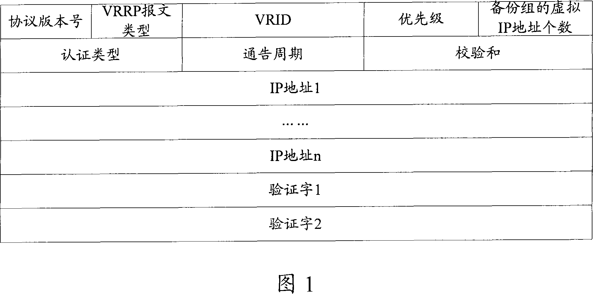
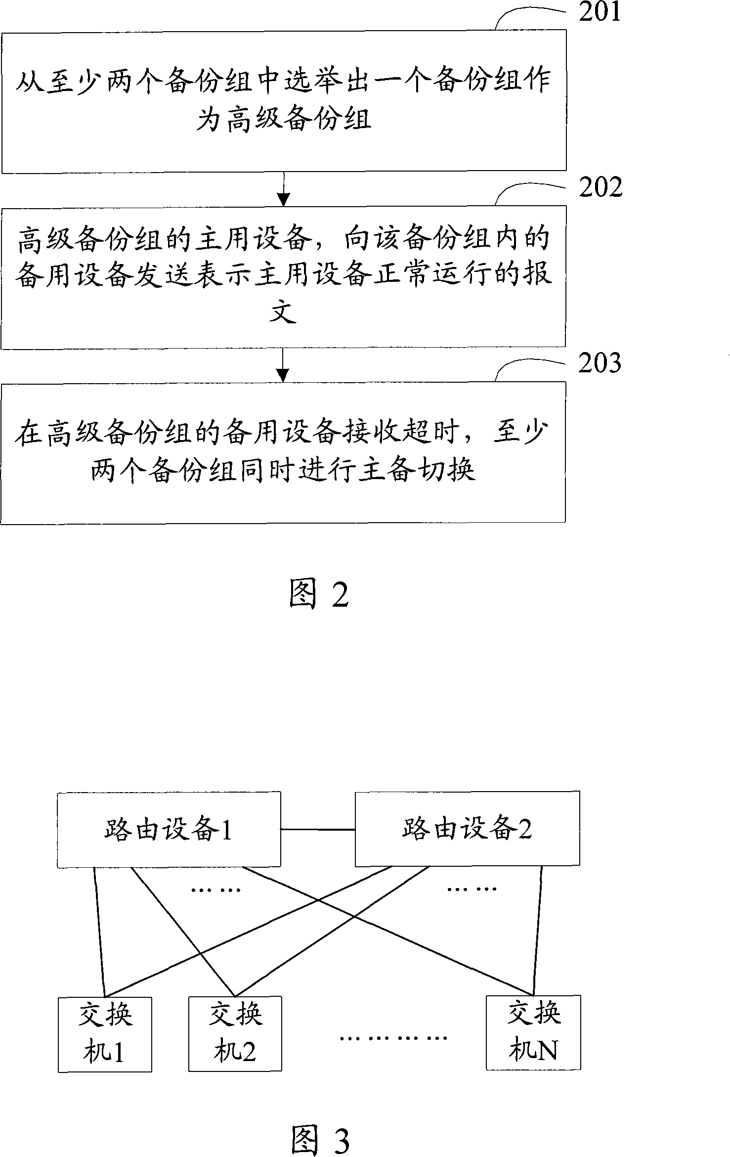
[0084] Take the Advertisement message indicating the normal operation of the active device as an example, assuming that routing device 1 and routing device 2 serve as 1000 backup groups at the same time, that is, N=1000, and the active devices of the 1000 backup groups are all routing devices 1. The backup devices of the 1000 backup groups are routing devices 2. In this way, to elect an advanced backup group, it is only necessary for the routing device 1 to send an Advertisement packet to the routing device 2 in each advertisement period, indicating that the primary device is running normally. Moreover, even if any number of backup groups with routing device 1 as the active device are added, the number of Advertisement packets between routing device 1 and routing device 2 is still one in each advertising period.

[0085] The traffic of 1000 switches is all forwarded by routing device 1. If the routing device 2, which is the backup device of the advanced backup group, receives...

example 2

[0088] Still taking the Advertisement message indicating the normal operation of the active device as an example, assuming that routing device 1 and routing device 2 serve as 1000 backup groups at the same time, that is, N=1000, and the active devices of 500 backup groups are routers Device 1 and backup device are routing device 2, and the active devices of the other 500 backup groups are routing device 2 and backup devices are routing device 1, that is, every 500 backup groups are bundled separately. In this way, a high-level backup group 1 is elected from 500 backup groups, and a high-level backup group 2 is elected from the other 500 backup groups, only routing device 1 needs to send a message to routing device 2 in each notification period The Advertisement message for the normal operation of the active device, the routing device 2 sends an Advertisement message indicating the normal operation of the active device to the routing device 1 in each advertisement period. Moreo...


PUM


Abstract

In the invention, the main equipment is a same route equipment, and the stand-by equipment is one of multi backup group in same route equipment; the main equipment only having one backup group sends a message for indicating the main equipment is in normal running state to the standby equipment in said backup group; if the receiving of message by the standby equipment in the standby group is over time, all standby groups simultaneously make man/standby switch. By the invention, the amounts of the messages between route devices will be not increased after the amount of backup group are increased.

Description

technical field [0001] The invention relates to master-standby switching technology, in particular to a method for master-standby switchover of routing equipment, a method for expanding the number of virtual router redundancy protocol (Virtual Router Redundancy Protocol, VRRP) backup groups, and a routing backup system. Background technique [0002] In the prior art, VRRP technology is usually used to enable multiple routing devices on the network side to support backup groups corresponding to different subnets, that is, one of the multiple routing devices serves as the master device of the backup group, and the other routing devices serve as backups. Group backup (Backup) devices, all routing devices in a backup group correspond to the same at least one virtual IP address. [0003] At any time, among multiple routing devices supporting a backup group, only one routing device is the active device of the backup group, and at least one other routing device is the backup device...

Claims


Application Information

Patent Timeline
IPC IPC(8): H04L12/24H04L29/06H04L12/56
CPCG06F11/2023
Inventor 邱元香
Owner NEW H3C TECH CO LTD
Why Eureka
Try Eureka