Centrifugal type fluid machine blade wheel

A fluid machinery, centrifugal technology, applied in mechanical equipment, liquid fuel engines, components of pumping devices for elastic fluids, etc. Achieve high anti-cavitation performance, improve impeller efficiency, and improve efficiency

Inactive Publication Date: 2008-01-02
高其海
View PDF1 Cites 10 Cited by
  • Summary
  • Abstract
  • Description
  • Claims
  • Application Information

AI Technical Summary

Problems solved by technology

[0003] However, in this impeller, the inlet of the impeller is narrow, and there is no transition space reserved at the outlet of the impeller flow channel, so the fluid will squeeze and rub against the fluid outside the impeller after flowing out of the impeller flow channel, thus The outflow of fluid is reduced, thereby reducing the efficiency of the impeller and wasting energy, thus limiting the application range of the impeller

Method used


Image

  • Centrifugal type fluid machine blade wheel
  • Centrifugal type fluid machine blade wheel

Examples


Embodiment 1

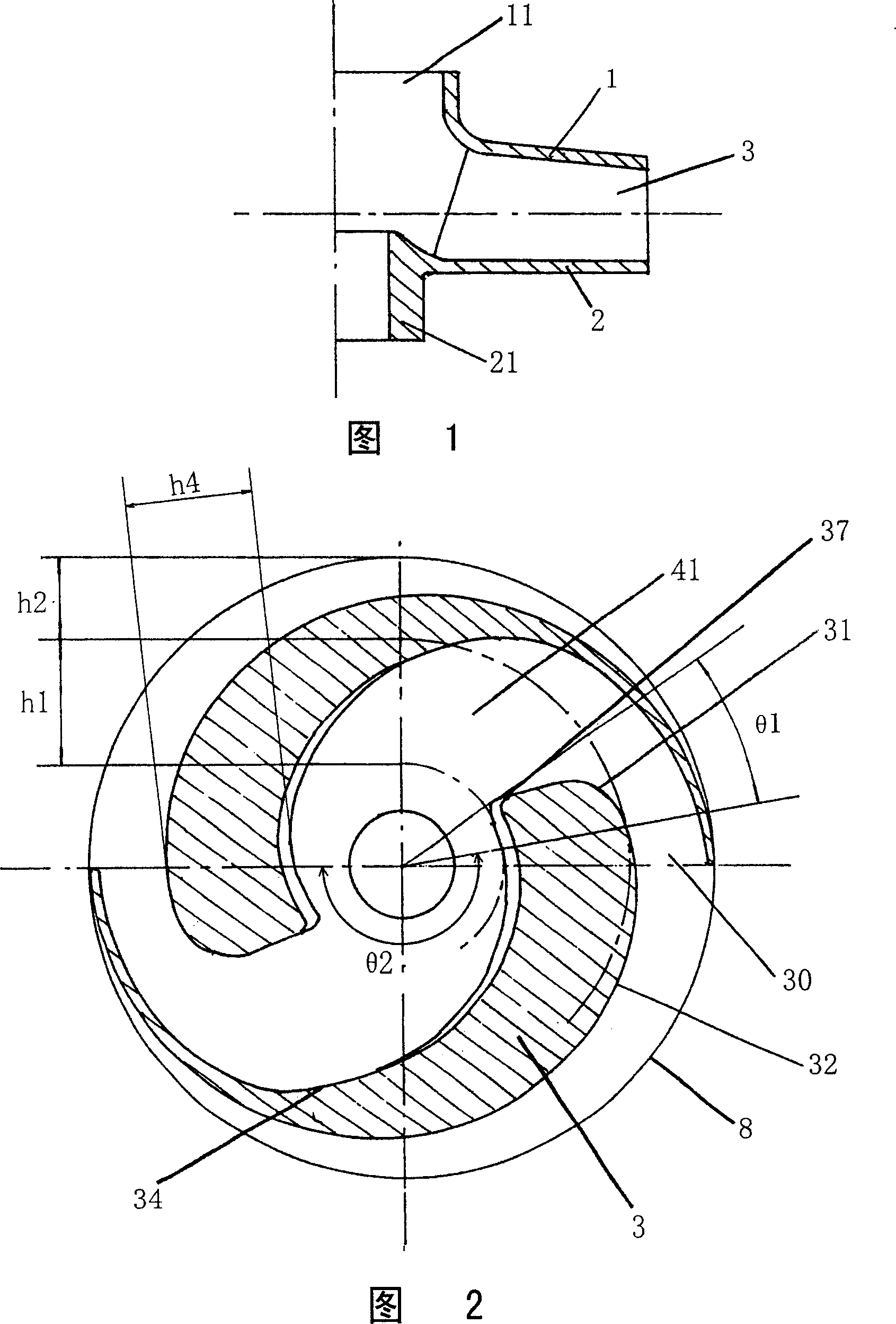
[0026] Figure 1 shows a first embodiment of the invention in which the impeller comprises two blades. As shown in FIG. 1 , the impeller according to the first embodiment of the present invention includes a front shroud 1 and a rear shroud 2 . Between the front cover plate 1 and the rear cover plate 2 there are two blades 3 distributed along the circumference, and the blades 3 are solid. The front cover 1 is integrated with the inlet 11 of the impeller, while the rear cover 2 is integrated with the hub 21 .

[0027] Fig. 2 is a top sectional view of Fig. 1 after cutting the front cover plate and part of the connected blades along the middle plane of the outlet between the two cover plates. As shown in FIG. 2 , the wrap angle of the front front section 31 of the blade 3 is θ1, and the radial extension is h1; the wrap angle of the front rear section 32 of the blade 3 is θ2, and the radial extension is h2.

[0028] Since the main function of the front front section 31 of the bla...

Embodiment 2

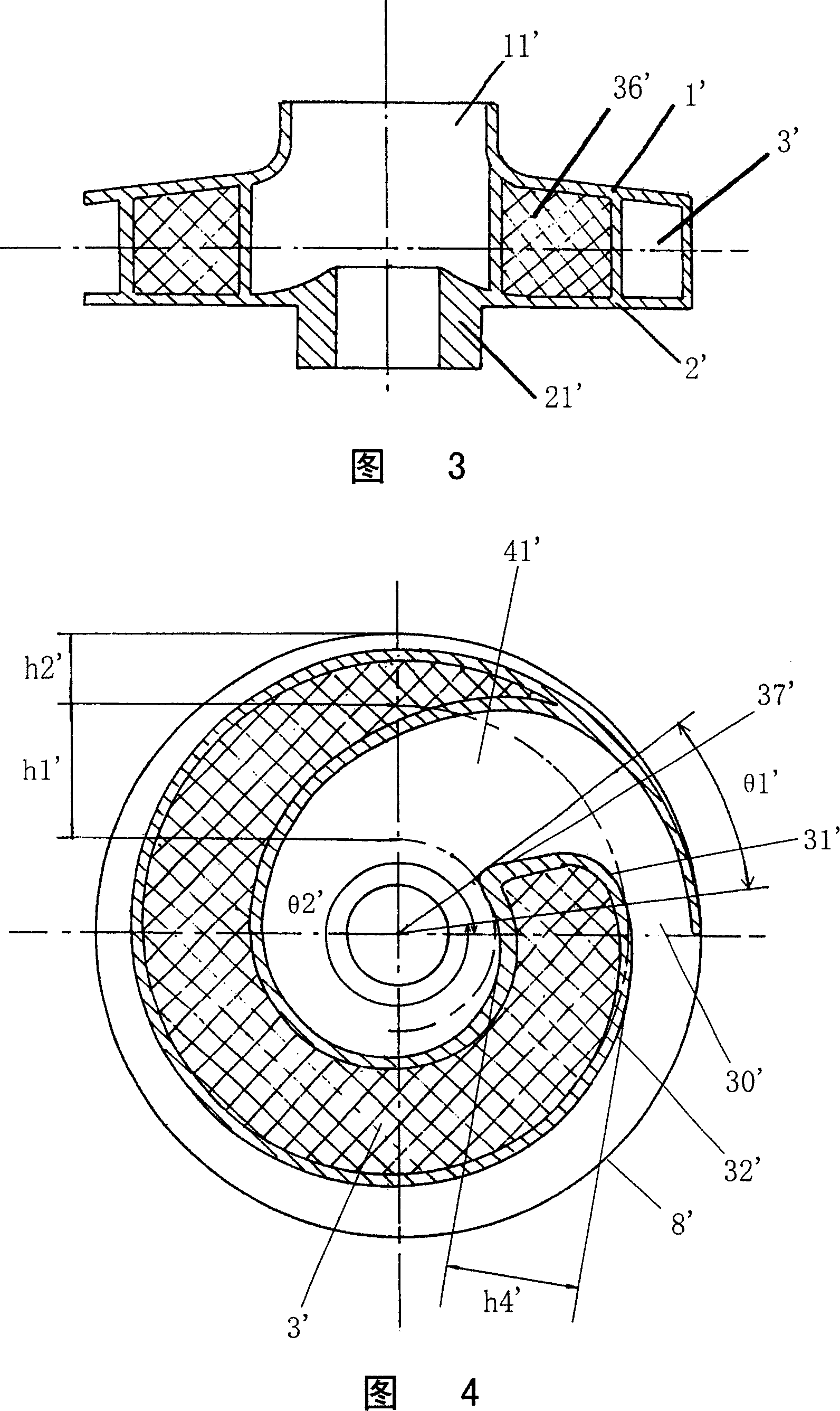
[0038] Figure 3 shows a second embodiment of the invention in which the impeller contains only one blade.

[0039] In the case of small flow rate, the impeller of the present invention can only have one blade, and the structure of this impeller has the following two differences from the structure of the impeller in the first embodiment of the present invention:

[0040] 1. The impeller with only one blade in the second embodiment of the present invention forms the inter-blade flow channel through the front and back of the blade itself.

[0041] 2. The impeller with only one blade in the second embodiment of the present invention needs to use conventional balancing techniques to solve the problem of unbalance of the impeller itself.

[0042] Since the rest of the structural features are the same as those of the impeller in the first embodiment of the present invention, they will not be repeated here.

[0043]As shown in Fig. 3, the impeller of the second embodiment of the pres...


PUM


Abstract

The invention discloses a centrifugal type fluid mechanical blade wheel, which is characterized by the following: comprising blade wheel inlet, boss, front shroud, back shroud and blade; possessing bigger curvature radius in the front of the face front segment of the blade; forming fore of flow passage between blade; bending the rear segment of the face front segment toward back; connecting to one integral with the face front segment of the blade; making the rear section of the flow passage between blade; possessing outlet along tangent direction near the blade wheel; displaying circumferential arc state near the blade wheel; forming a transition space from the outlet of the blade wheel to the rear end of the blade. This invention can increase the efficiency of the blade wheel.

Description

technical field [0001] The invention relates to an impeller, in particular to a centrifugal fluid mechanical impeller which can be used for a centrifugal pump or a centrifugal fan. This kind of impeller has a front cover and a rear cover, wherein the front cover is integrated with the inlet of the impeller, and the rear cover is integrated with the hub. thick leaves. Background technique [0002] In the prior art, for example, Chinese Patent No. 01272927 discloses a centrifugal fluid mechanical impeller. In this impeller, a design of thick blades and gradually shrinking and back-curved inter-blade flow passages is adopted. This thick blade can greatly reduce the wetted peripheral area, thereby increasing the efficiency of the impeller. In addition, the gradually shrinking inter-blade flow channel can also effectively suppress the separation phenomenon in the flow channel. Therefore, this impeller has relatively high efficiency and anti-cavitation performance. [0003] H...

Claims


Application Information

Patent Timeline
Patent Type & Authority Applications(China)
IPC IPC(8): F04D29/24F04D29/30
Inventor 高其海
Owner 高其海
Why Eureka
Try Eureka