Magnetic recording element and magnetic memory
一种磁性存储器、磁性记录的技术,应用在静态存储器、只读存储器、数字存储器信息等方向,能够解决热波动阻抗和再现信号幅度输出恶化等问题
- Summary
- Abstract
- Description
- Claims
- Application Information
AI Technical Summary
Problems solved by technology
Method used
Image

Examples
no. 1 example
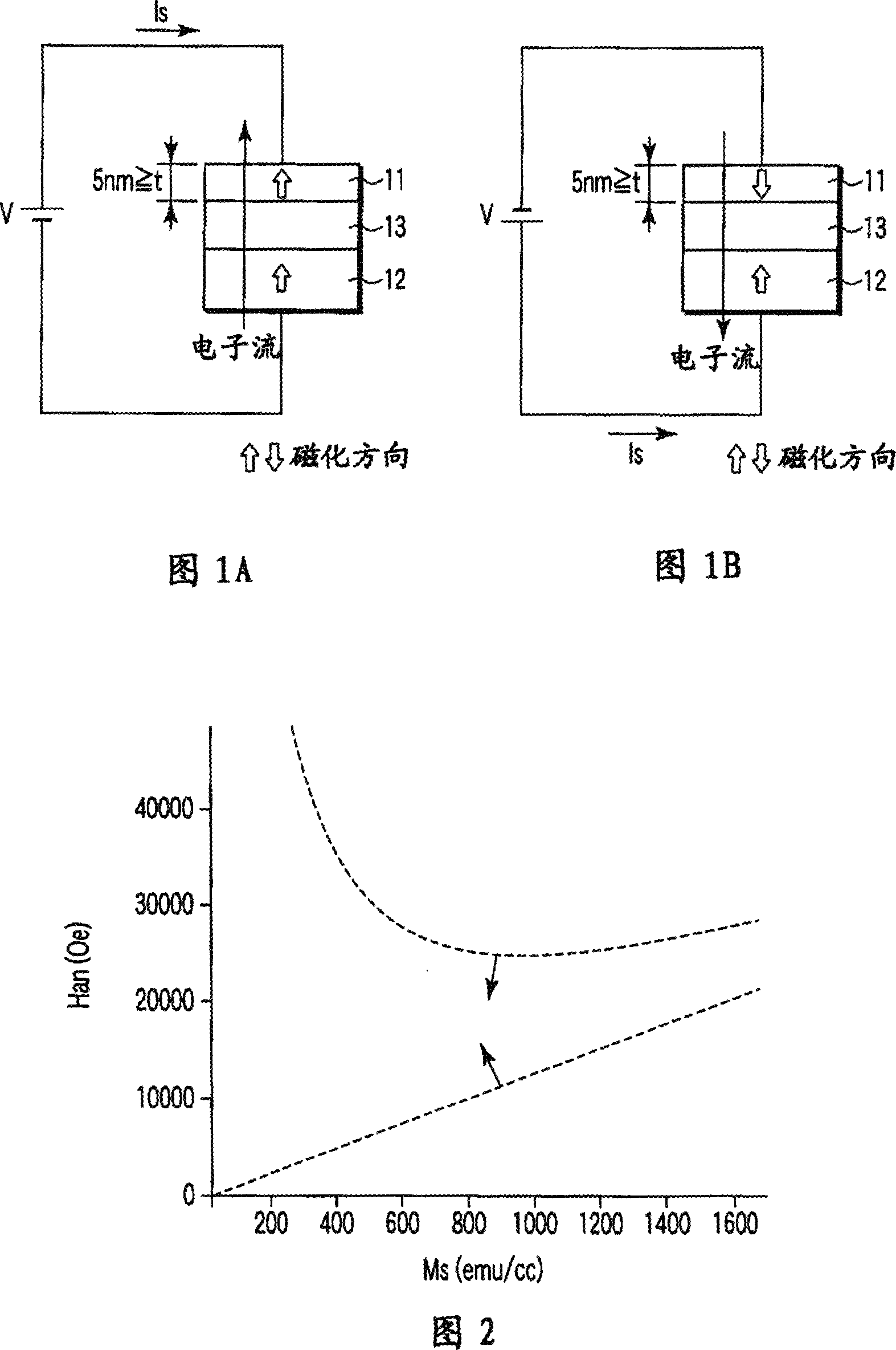
[0064] 1A and 1B are side views showing the structure of the magnetic recording element of the first embodiment.
[0065] The magnetic free layer 11 has variable magnetization, and the direction of the easy axis of magnetization thereof is in a direction perpendicular to the film plane. The magnetic pinned layer 12 has magnetization fixed in a direction perpendicular to the film plane. A non-magnetic barrier layer 13 is provided between the magnetic free layer 11 and the magnetic pinned layer 12.
[0066] The magnetic free layer 11 is composed of a magnetic material in which the relationship between the saturation magnetization Ms (emu / cc) and the anisotropic magnetic field Han (Oe) satisfies Han>12.57Ms and Han-1 +12.57Ms, and its thickness is 5nm or less.
[0067] The magnetic pinned layer 12 is composed of a magnetic material. Due to, for example, the antiferromagnetic layer, the magnetization direction of the magnetic pinned layer 12 is fixed. The non-magnetic barrier layer 13...
no. 3 example
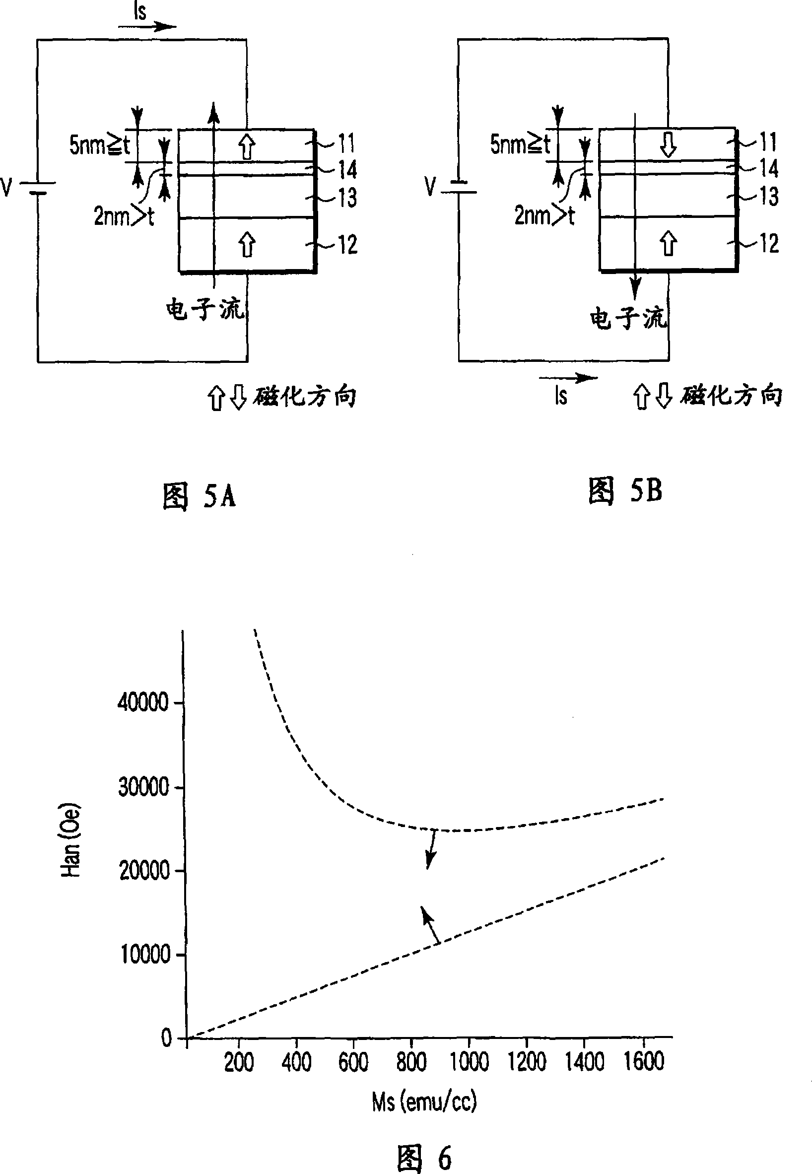
[0085] 5A and 5B are side views showing the structure of the magnetic recording element of the third embodiment.
[0086] The magnetic free layer 11 has variable magnetization, and the direction of the easy axis of magnetization is a direction perpendicular to the film plane. The magnetic pinned layer 12 has a fixed magnetization in a direction perpendicular to the film plane. A non-magnetic barrier layer 13 is provided between the magnetic free layer 11 and the magnetic pinned layer 12, and an insertion layer 14 is provided between the magnetic free layer 11 and the non-magnetic barrier layer 13.
[0087] The magnetic free layer 11 is composed of a magnetic material, in which the relationship between the saturation magnetization Ms (emu / cc) and the anisotropic magnetic field Han (Oe) satisfies Han>12.57Ms and Han-1 +12.57Ms, and its thickness is 5nm or less.
[0088] Also, the insertion layer 14 is composed of a magnetic material, and its saturation magnetization Ms is set to a v...
no. 4 example
[0099] 12 to 14 are views showing the structure of the magnetic recording element of the fourth embodiment.
[0100] The magnetic free layer 11 is composed of magnetic fine particles 101 spatially separated from the non-magnetic material 16, the magnetization of the magnetic fine particles 101 is variable, and the direction of the easy axis of magnetization is in the direction perpendicular to the film plane.
[0101] The magnetic pinned layer 12 has a fixed magnetization in a direction perpendicular to the film plane. A non-magnetic barrier layer 13 is provided between the magnetic free layer 11 and the magnetic pinned layer 12. A cap layer 15 is provided on the magnetic free layer 11.
[0102] The magnetic fine particles 101 are composed of a magnetic material in which the relationship between the saturation magnetization Ms (emu / cc) and the anisotropic magnetic field Han (Oe) satisfies Han>12.57Ms and Han-1 +12.57Ms, and its thickness is 10nm or less.
[0103] The magnetic pinned...
PUM
 Abstract
Description
Claims
Application Information
PatSnap Eureka turns technology decisions into work you can execute. Powered by our Innovation Knowledge Graph, it runs expert workflows across engineering, life sciences, materials and intellectual property. Get your review-ready output in minutes.


