Finish rolling machine strip steel threading between frames movable sleeve controlling method

A control method and inter-stand technology, applied in rolling mill control devices, metal rolling, metal rolling, etc., can solve problems such as lower surface scratches, reduce roll surface damage, improve strip surface quality, and reduce maintenance Effect of Repair and Spare Parts Costs

Active Publication Date: 2008-01-09
BAOSHAN IRON & STEEL CO LTD
View PDF0 Cites 29 Cited by
  • Summary
  • Abstract
  • Description
  • Claims
  • Application Information

AI Technical Summary

Problems solved by technology

[0006] The main purpose of the present invention is to solve the scratch defect on the lower surface of the strip between the existing finishing stands, avoid the method that the operator adopts the method of increas...

Method used


Image

  • Finish rolling machine strip steel threading between frames movable sleeve controlling method
  • Finish rolling machine strip steel threading between frames movable sleeve controlling method
  • Finish rolling machine strip steel threading between frames movable sleeve controlling method

Examples


Embodiment Construction

[0018] The electromechanical implementation conditions of the finishing rolling looper control method and the control method of the present invention:

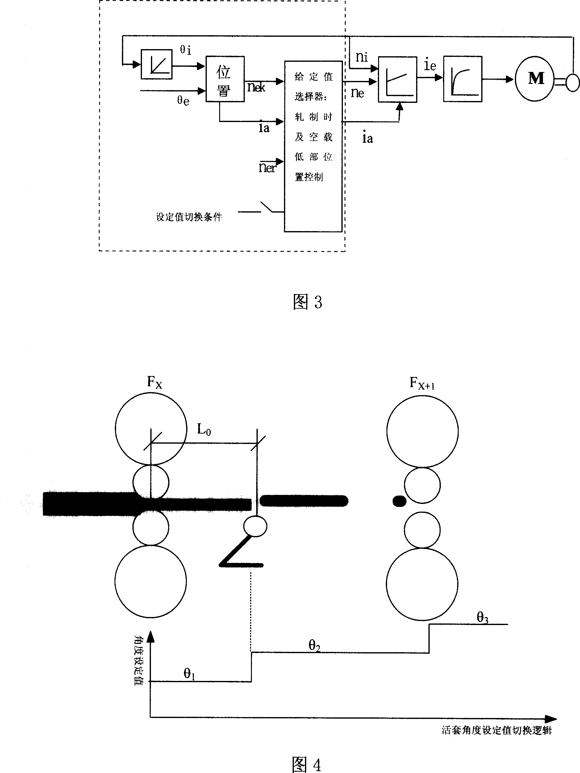
[0019] 1. Mechanical conditions: The prerequisite for the realization of the above technical scheme is to improve the lower end position on the relevant mechanical equipment, redesign the lower end position of the looper roll, and ensure that the upper busbar of the looper roll is always lower than the actual rolling line to ensure that the looper The position of the lower end of the support can be flexibly controlled according to different angle requirements.

[0020] The lower end of the looper holder of the prior art is the looper roller waiting position, and the general adjustment angle is 4°~11°. Because the lower end is subject to friction, the initial angle of the looper supporter is not easy to accurately calibrate, and the position of the lower end of the looper roll is the same as the initial angular position of the ...


PUM


Abstract

The loop control process for threading strip steel into finishing mill includes the following steps: making the looper roll in the initial angle automatically calibrated with the angle generator; making the loop in the stand-by angle when the strip steel enters to the front platen; making the looper roll in the threading angle after the head of the strip steel is sucked into the front platen and passed through the looper roll; raising the loop for the looper roll bus line to be lower than the lowest rolling line after the head of the strip steel enters to the back platen; and lowering the loop and entering to the ready position. The automatic control process can avoid faults in the strip steel effectively.

Description

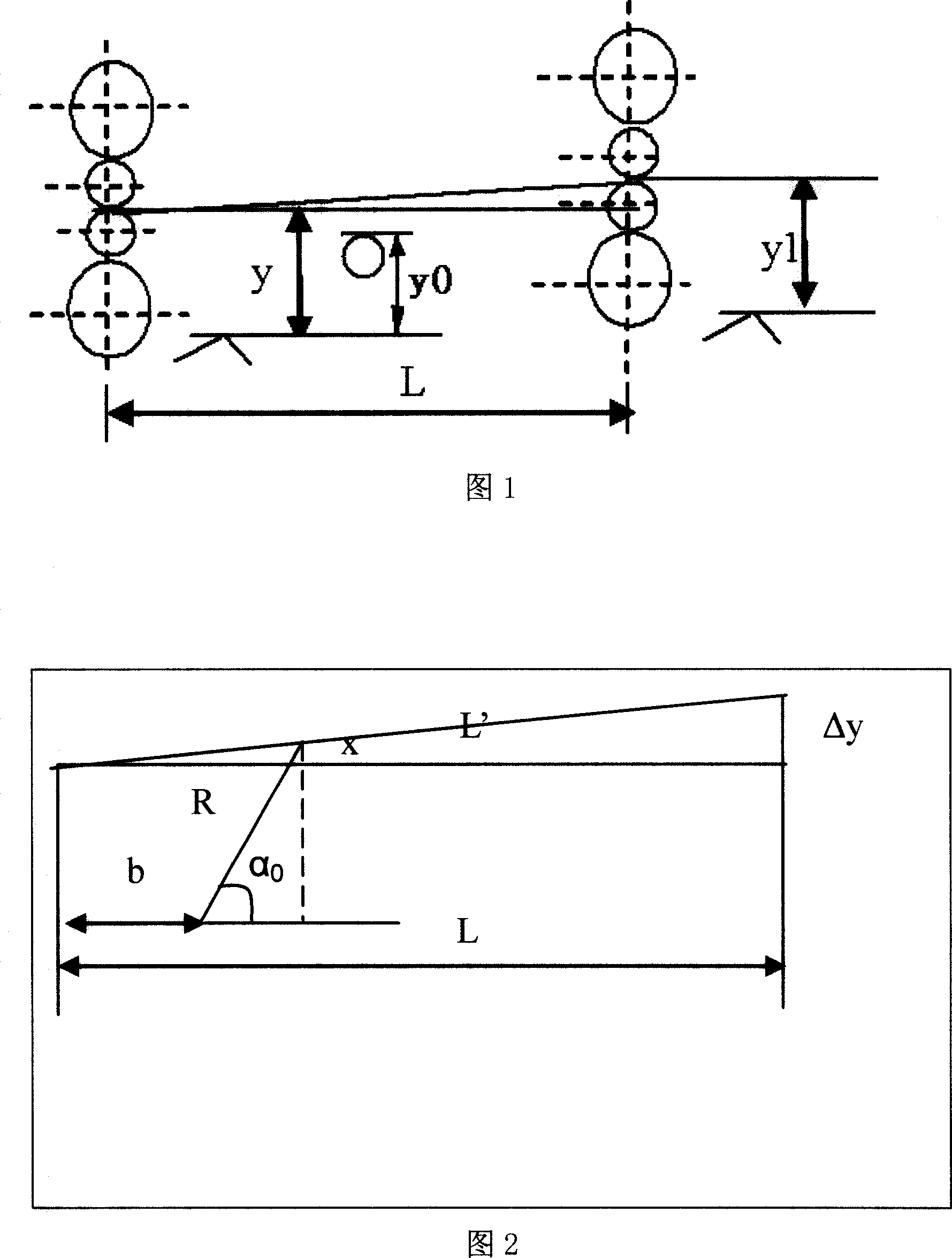
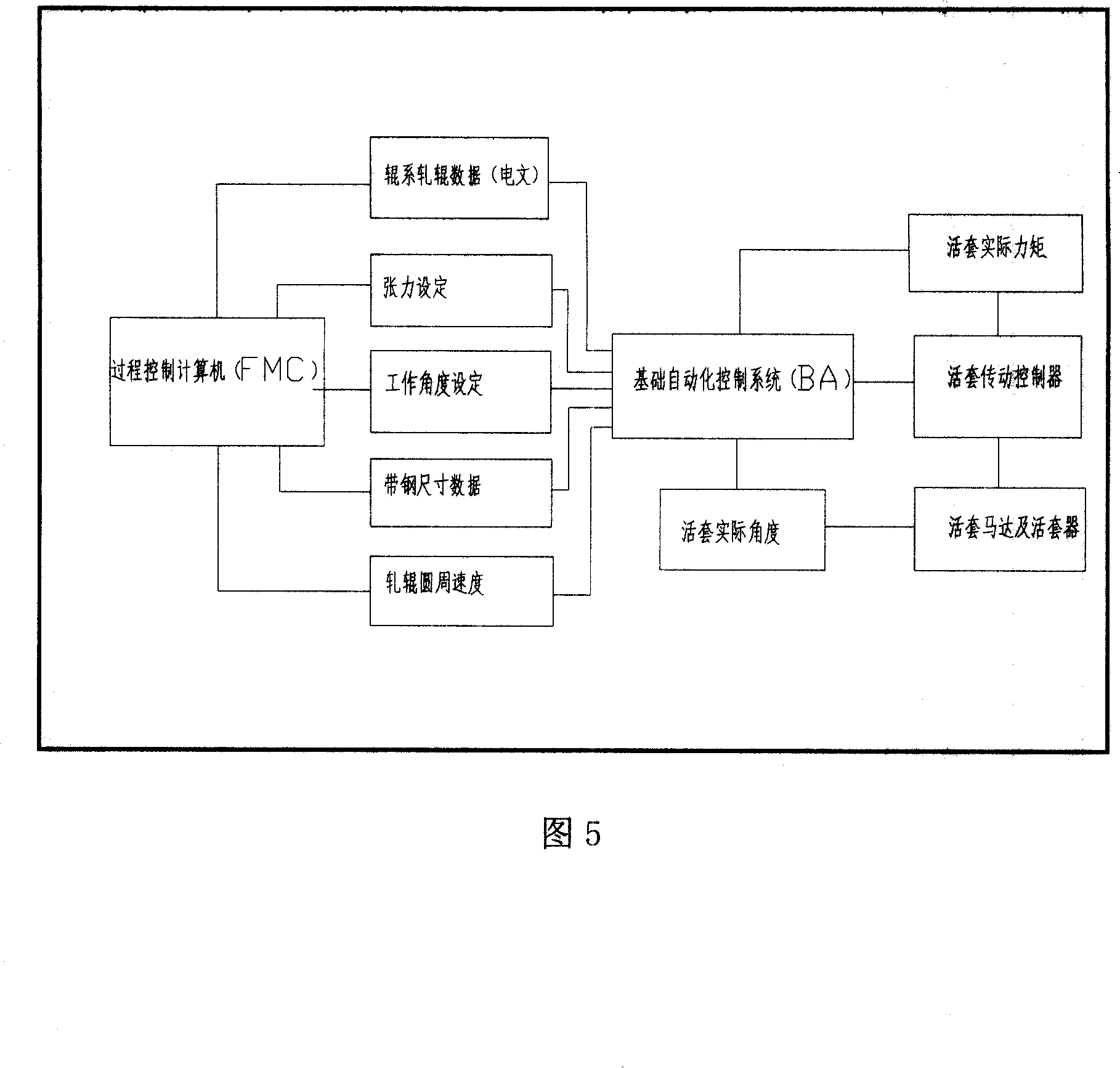
technical field [0001] The invention relates to a looper automatic control technology, in particular to a looper control method during strip threading between finishing stands. Background technique [0002] In iron and steel enterprises at home and abroad, the looper is a device used to support the strip steel, form a certain amount of sleeve, and keep the flow and tension between the stands constant in the process of hot rolling and finishing rolling. Baosteel 2050 hot rolling finish rolling looper adopts electric looper with constant tension control. The change of the angle of the swing arm of the looper is detected by the angle generator, the current of the torque motor is set through the torque calculation, and the set amount is calculated to adjust the main drive at the same time, so as to realize the control of the tension between the racks and the flow of the strip steel. The set amount refers to the strip length between the racks that exceeds the rack spacing. Duri...

Claims


Application Information

Patent Timeline
IPC IPC(8): B21B37/00B21B41/00
Inventor 杨春平王军陈志荣苗润涛陈占福
Owner BAOSHAN IRON & STEEL CO LTD
Why Eureka
Try Eureka