Detecting device

A detection device and detection rod technology, which is applied in the direction of measuring/indicating equipment, metal processing machinery parts, metal processing equipment, etc., can solve the problems of different detection requirements and inaccurate detection, and achieve wide adaptability, high motion precision, The effect of easy operation

Inactive Publication Date: 2008-01-09
SHANDONG FIN CNC MACHINE
View PDF0 Cites 19 Cited by
  • Summary
  • Abstract
  • Description
  • Claims
  • Application Information

AI Technical Summary

Problems solved by technology

[0007] In order to solve the problems of inaccurate detection and different detection requirements of different workpiece conditions in the prior art, the present invention provides a non-lateral thrust, and when the workpiece is in a free state, as long as different detection rods are designed according to the shape of the workpiece, A detection device that can detect profiles, plates, pipes, etc.

Method used


Image

  • Detecting device
  • Detecting device
  • Detecting device

Examples


Embodiment Construction

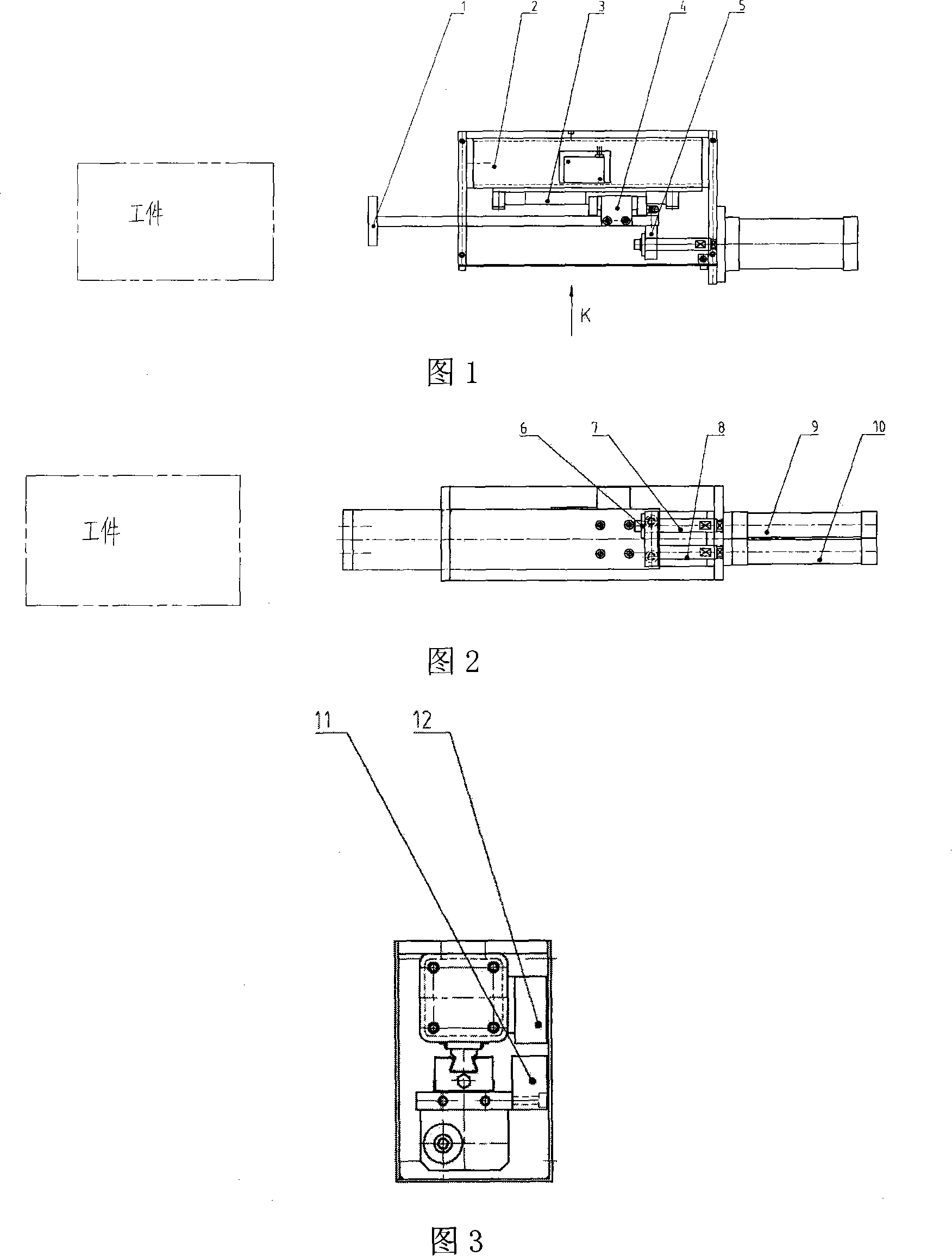
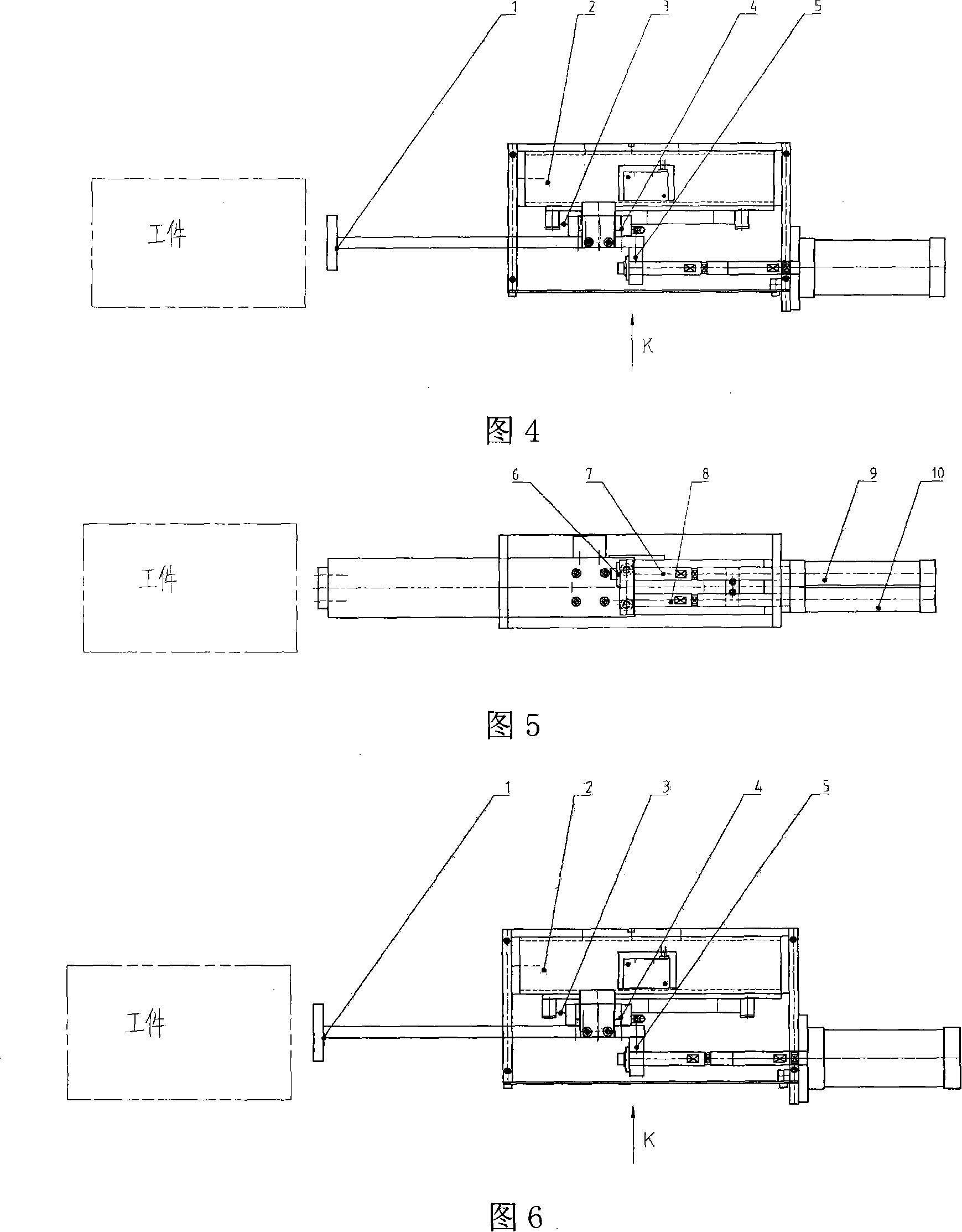
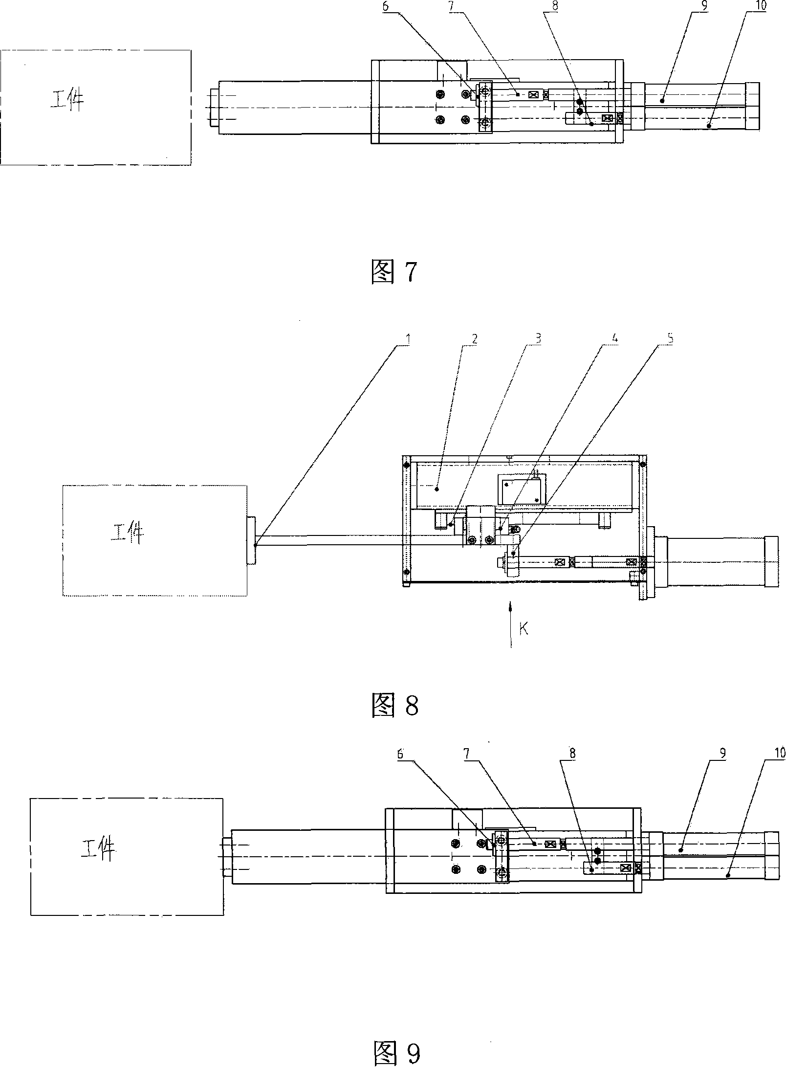
[0040] A detection device as shown in Figures 1 to 13, including a detection rod 1, a cylinder behind the detection rod 1 that can push the detection rod 1 to move, a linear guide rail 3 for making the detection rod 1 move linearly, and a The guide rail mounting base 2 of the linear guide rail 3 and the guide rail slider 4 , the position sensor 12 fixed on the guide rail mounting base 2 and the sensing block 11 installed on the detection rod 1 that can move with the detection rod 1 .

[0041] Among them, the linear guide rail pair composed of the linear guide rail 3 and the guide rail slider 4 mainly plays the role of guiding and positioning to ensure the accuracy of the detection device; the detection rod 1 is installed on the guide rail slider 4, and it mainly plays the role of contacting the workpiece; The main function of the position sensor 12 is to detect the position of the sensing block 11 so as to issue instructions to the control system.

[0042] There are two cylind...


PUM


Abstract

The present invention relates to one kind of detection device for detecting position deviation or contour deviation of workpiece. The detection device includes one test rod, test rod driving cylinders, one track for the test rod to move linearly, one pedestal for the track to be fixed on, one position sensor fixed on the pedestal, and one sensing block on the test rod. Two cylinders include one connected to the test rod through one push rod and one other connected to the test rod through one pull rod. The present invention may be applied in detecting sections, plates, pipes, etc by using different test rods designed based on the shapes of the workpieces to be detected, and has wide application range, easy manufacture and high practicability.

Description

(1) Technical field [0001] The invention relates to a measuring device of a machine tool, in particular to a detection device without lateral thrust and capable of detecting the position or shape deviation of a workpiece. (2) Background technology [0002] When processing a workpiece, it is often necessary to detect the position or shape deviation of the workpiece. The detection methods are generally divided into two types: contact type and non-contact type. [0003] Both forms of detection have disadvantages: [0004] 1. Contact detection device, although it has no special requirements on the use environment, material and distance of the workpiece, but it often loads a large or small additional thrust on the workpiece at the moment of contact with the workpiece, which will affect the detection accuracy of the workpiece, especially When the workpiece is in an unclamped state. [0005] 2. Although the non-contact detection device does not generate additional thrust, it has ...

Claims


Application Information

Patent Timeline
Patent Type & Authority Applications(China)
IPC IPC(8): B23Q17/22B23Q17/20
Inventor 孙军丁刚田惠秋张珂
Owner SHANDONG FIN CNC MACHINE
Why Eureka
Try Eureka