

Steel rail space adjuster
A technology of adjuster and gauge, applied in the direction of track, laying track, measuring instrument, etc., can solve the problems of unsuitable high-speed passenger dedicated line laying and maintenance, etc., and achieve the effect of safe use, fast adjustment and convenient portability
- Summary
- Abstract
- Description
- Claims
- Application Information
AI Technical Summary
Problems solved by technology
Method used
Image

Examples
Embodiment Construction
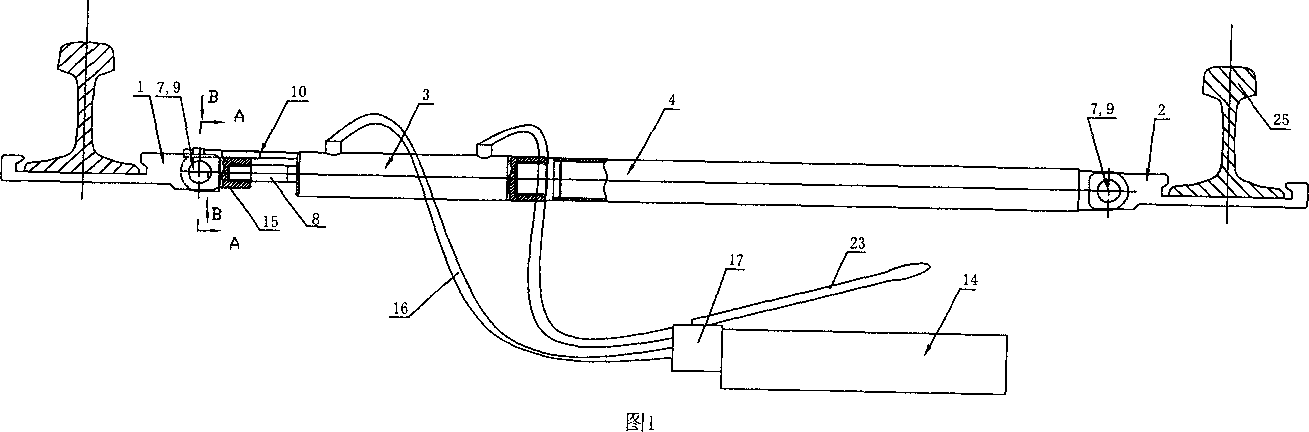
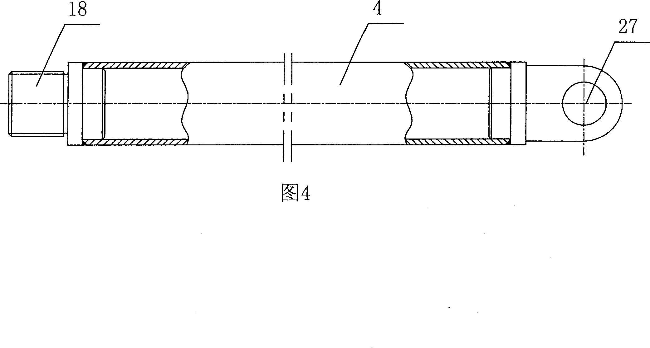
[0036] The rail gauge adjuster shown in Figure 1 includes a connecting rod 4 whose right end is insulatedly connected to the right deck 2, and the left end is connected to the hydraulic cylinder 3. The piston rod connector 15 of the hydraulic cylinder 3 is insulated and connected to the left deck 1. The rod connector 15 is equipped with a scale 10 that can be elastically stretched between the piston rod connector 15 and the cylinder head of the hydraulic cylinder 3. The hydraulic cylinder 3 is connected to the hydraulic control pump 17 through the oil pipe 16, and the hydraulic control pump 17 is connected to the oil cylinder 14. .
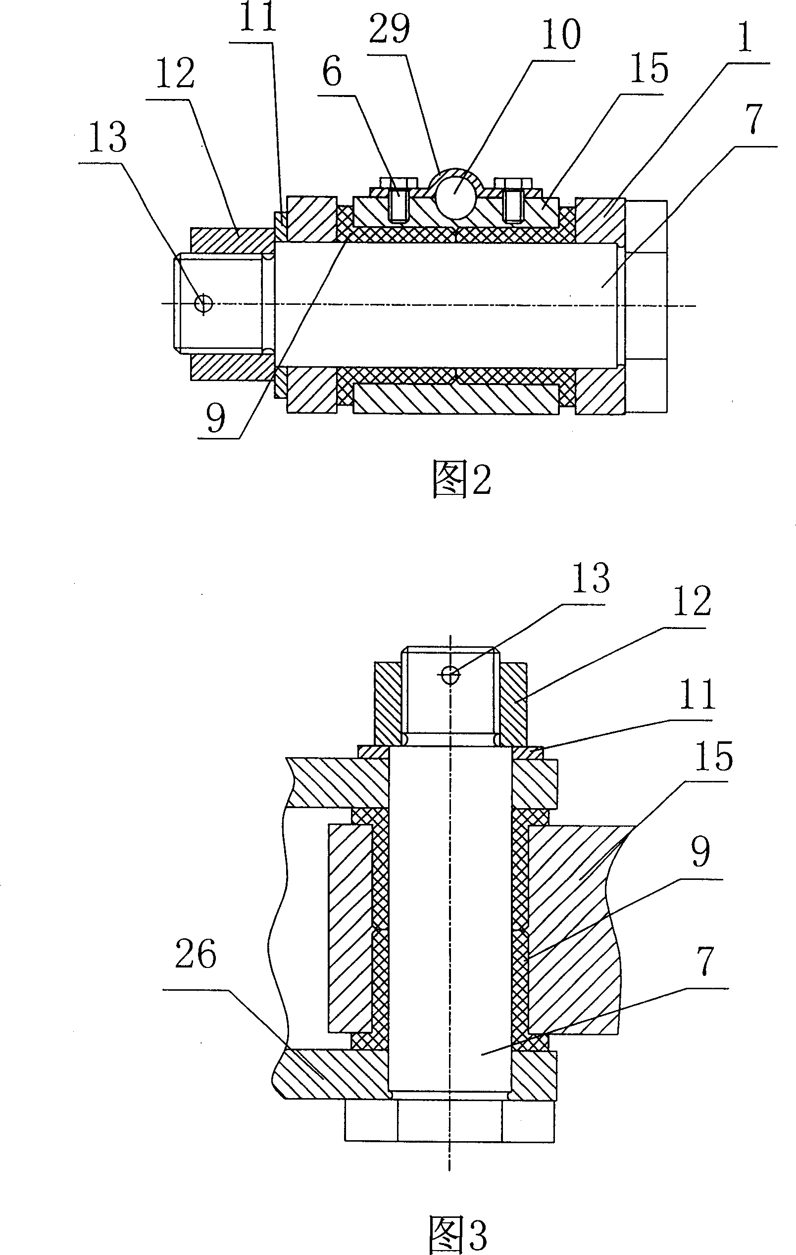
[0037] As shown in Fig. 3, Fig. 6 and Fig. 7, the inner ends of the left card holder 1 and the right card holder 2 for clamping the rail 25 are correspondingly provided with axial connecting plates 26 with radial concentric holes. As shown in FIG. 5 , the inner end of the connecting head 15 of the piston rod of the hydraulic cylinder 3 is provided...
PUM
 Abstract
Description
Claims
Application Information