

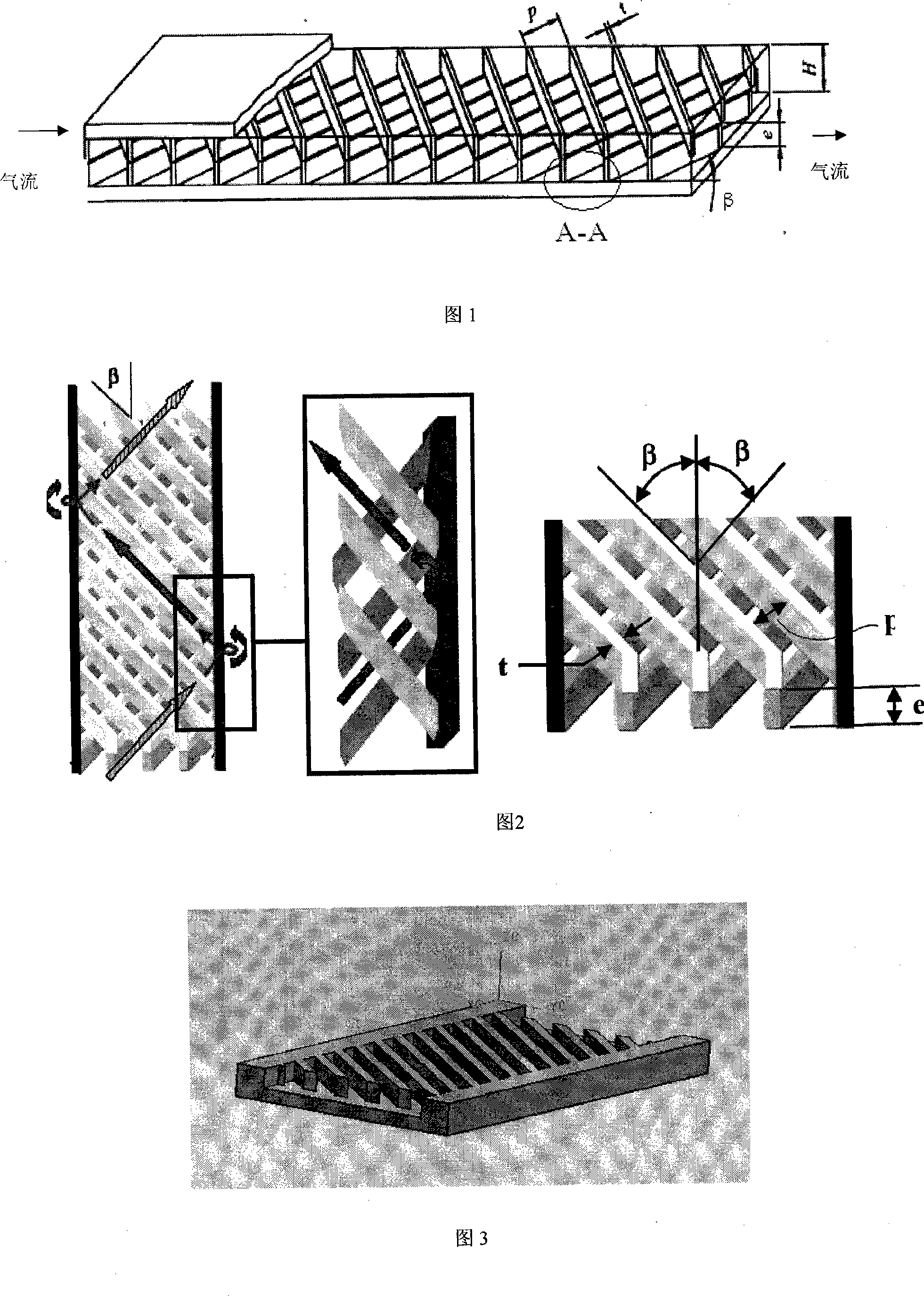
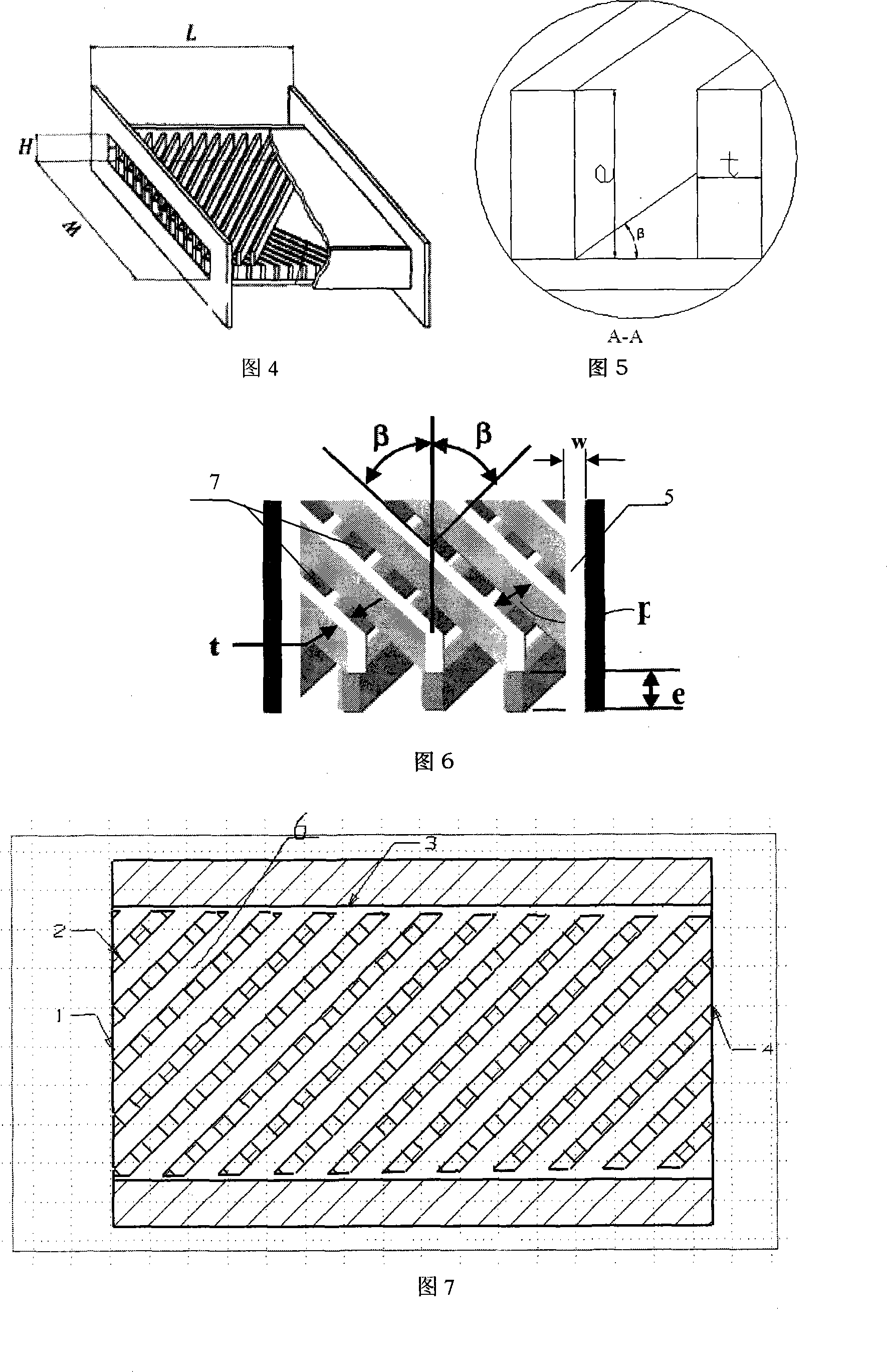
Gradually widened slot staggered rib passage suitable for internal cooling member as turbine blade
A technology of staggered ribs and cooling channels, applied in the directions of blade support elements, engine elements, machines/engines, etc., can solve the problems of large pressure loss and low utilization rate of cold air, and achieve thermal stress reduction and heat transfer uniformity optimization. , the effect of reducing the flow resistance
- Summary
- Abstract
- Description
- Claims
- Application Information
AI Technical Summary
Problems solved by technology
Method used
Image

Examples
Embodiment Construction
[0021] The present invention will be further described in detail below in conjunction with the accompanying drawings.
[0022] The present invention is the conclusion that researches its heat transfer and flow resistance characteristic through simplified model experiment and three-dimensional numerical simulation, the heat transfer and flow resistance characteristic of straight slot (5) interlaced rib passage are studied with the change of groove width w in experiment and numerical value This regularity is found when changing relationships. The research results show that the drag coefficient of the channel decreases with the increase of the groove width w. The heat transfer effect of the channel increased by slotting is mainly concentrated in the first half of the fluid flow, and the influence of different slot widths on the second half of the channel is not much different. Therefore, it can be considered to select the groove width w corresponding to the best heat transfer ef...
PUM
 Abstract
Description
Claims
Application Information