Automatic speed derailleur for electric vehicle

A technology of automatic transmission and electric vehicle, applied in the direction of transmission, gear transmission, belt/chain/gear, etc., can solve the problems of excessive battery discharge current, reduced battery life, limited driving speed, etc., to prolong the service life , Enhanced adaptability, compact effect

Inactive Publication Date: 2008-01-09
赵国志
View PDF0 Cites 4 Cited by
  • Summary
  • Abstract
  • Description
  • Claims
  • Application Information

AI Technical Summary

Problems solved by technology

The ratio of power input to output is a constant value, which limits the speed of the vehicle, and the motor cannot work in the optimal area due to different road conditions and large changes in driving resistance.
When the driving resistance is too large, the motor works in a locked-rotor state, which will cause excessive discharge current of the battery and reduce battery life, and even burn the motor in severe cases.

Method used


Image

  • Automatic speed derailleur for electric vehicle
  • Automatic speed derailleur for electric vehicle
  • Automatic speed derailleur for electric vehicle

Examples


Embodiment 1

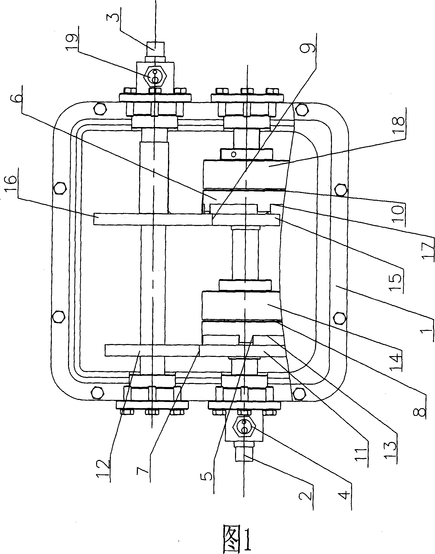
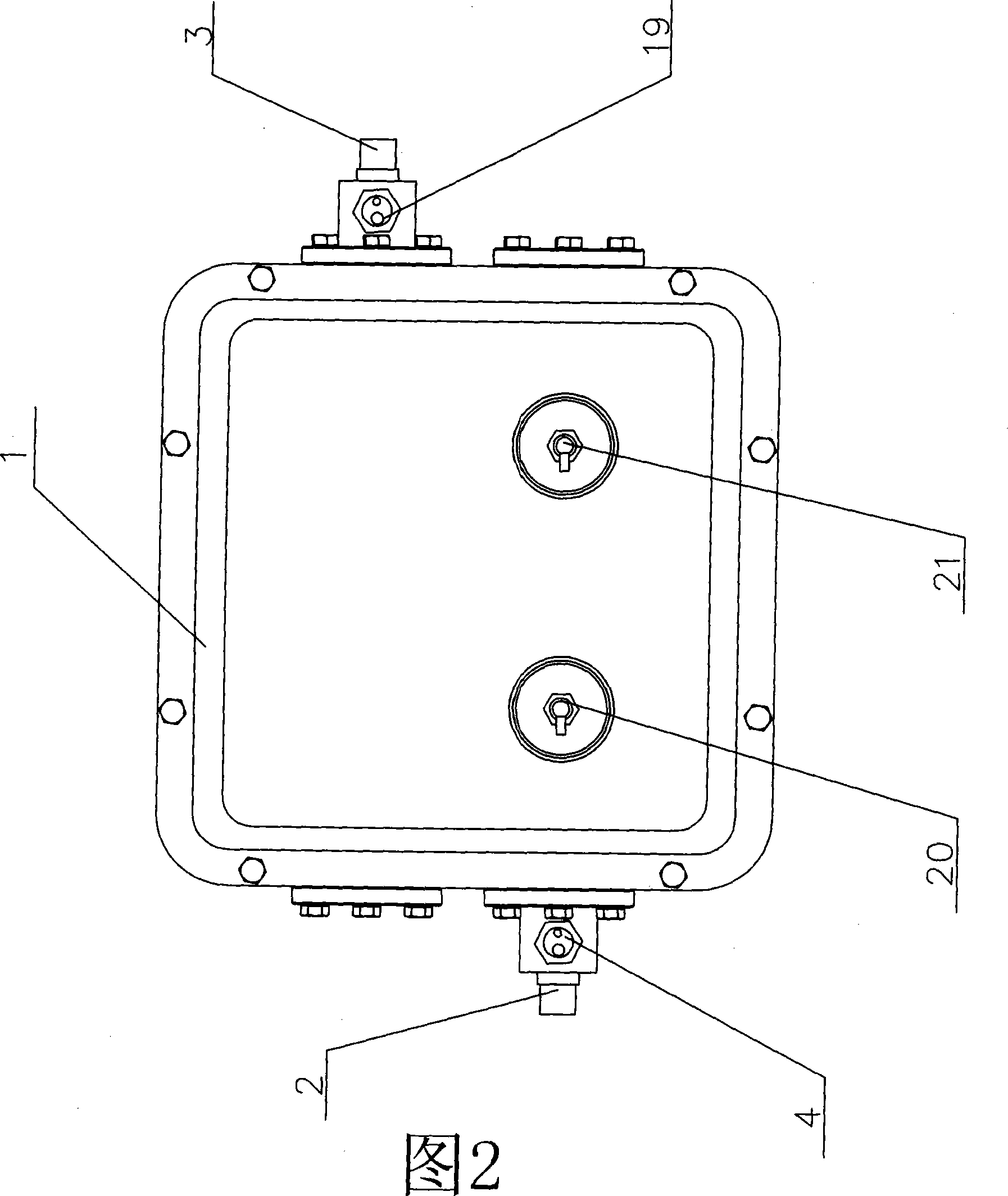
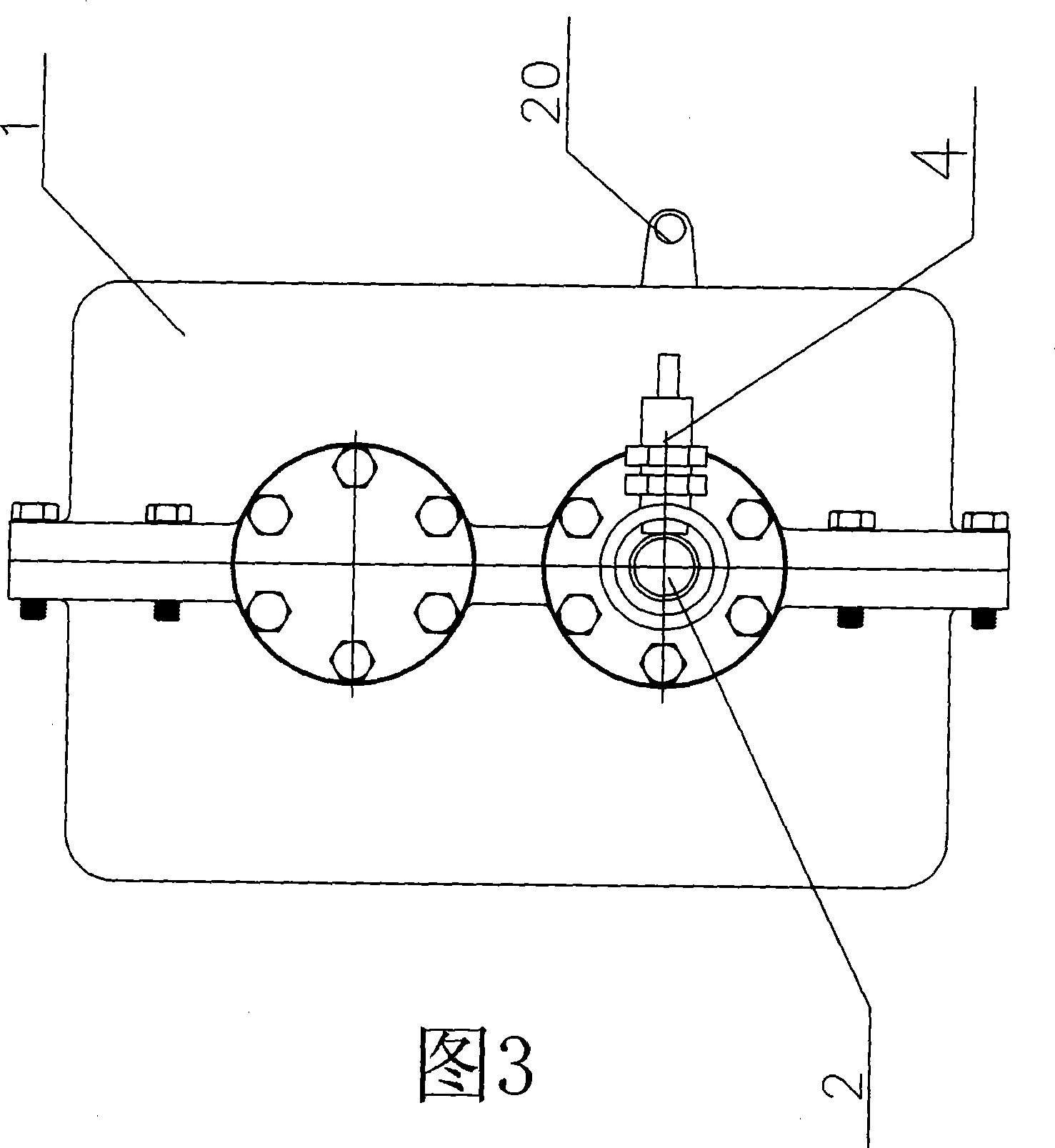
[0021] Embodiment 1: (shown in Fig. 1, Fig. 2, Fig. 3), electric vehicle automatic transmission (two groups of speed change mechanisms) comprises casing 1, power input shaft 2, power output shaft 3, links to each other with power input shaft 2 Input rotational speed sensor 4, input rotational speed sensor 4 is placed outside machine case 1, is provided with two speed change mechanisms in machine case 1-high-speed speed change mechanism 5 and low-speed speed change mechanism 6, wherein high-speed speed change mechanism 5 includes high-speed gear set 7 and high-speed clutch 8. The low-speed transmission mechanism 6 includes a low-speed gear set 9 and a low-speed clutch 10, wherein the high-speed gear set 7 includes a high-speed input gear 11 and a high-speed output gear 12, and the high-speed input gear 11 and the high-speed output gear 12 have the same number of teeth (that is, constant velocity). The high-speed input gear 11 is connected to the driven end 13 of the high-speed ...

Embodiment 2

[0023] Embodiment 2: (as shown in Fig. 4, Fig. 5), electric vehicle automatic transmission (three groups of speed change mechanisms) comprises casing 1, power input shaft 2, power output shaft 3, the input rotational speed sensor that links to each other with power input shaft 2 4. The input rotational speed sensor 4 is placed outside the case 1, and three speed change mechanisms are arranged in the case 1 - a high-speed speed change mechanism 5, a low-speed speed change mechanism 6 and a medium-speed speed change mechanism 22, wherein the high-speed (constant speed) gear of the high-speed speed change mechanism 5 Group 7 includes a high-speed input gear 11 and a high-speed output gear 12, and the high-speed input gear 11 and the high-speed output gear 12 have the same number of teeth, the high-speed input gear 11 is connected with the high-speed clutch passive end 13, and the high-speed clutch active end 14 is connected to the power input through a fixed key. Axis 2 is connect...

Embodiment 3

[0035] Embodiment 3: As shown in FIG. 6 and FIG. 7 , the electric vehicle automatic transmission includes a casing 1 , a power input shaft 2 , a power output shaft 3 , and an input speed sensor 4 connected to the power input shaft 2 . The input speed sensor 4 is placed outside the cabinet 1, and five speed change mechanisms-overspeed speed change mechanism 35, direct speed change mechanism 36, high speed speed change mechanism 5, middle gear speed change mechanism 22 and low speed speed change mechanism 6 are provided in the casing 1.

[0036] The overdrive transmission mechanism 35 is composed of an overdrive input gear 37 , an overdrive output gear 38 , and an overrun clutch 39 . The overrunning input gear 37 is connected with the driven end 40 of the overrunning clutch 39; the overrunning output gear 38 is connected with the power output shaft 3 through a fixed key;

[0037] The direct transmission mechanism 36 is composed of a direct input gear 42 , a direct output gear 43...


PUM


Abstract

This invention discloses motor vehicle automatic transmission. It includes machine case; power input shaft; power output shaft and input rotation rate sensor connected with power input shaft. There are at least two speed changing mechanisms in the machine case. The input gear of speed changing mechanism gear cluster connects to the passive end of clutch. The active end of clutch connects to power input shaft. The output gear of gear cluster connects to power output shaft. There is output rotation rate sensor on the output end of power output shaft. The external part of machine case is arranged with clutch brushes which are respectively connected with speed changing mechanism clutches. The output power of this invention is smooth, which makes the vehicle better adaptability to roads. This invention also makes the machine long life span. It can be applied on booster device such as motor traveling car, motor tricycle and motor vehicle.

Description

Technical field: [0001] The invention relates to an automatic transmission, in particular to an automatic transmission used on an electric vehicle. Background technique: [0002] Nowadays, a group of passenger and cargo fuel motorcycles are active in small towns and suburban areas of cities in all provinces of the country. Fuel motorcycles pollute the atmosphere very badly. With the reduction of non-renewable energy, the quality of the environment is directly threatened people's health. Therefore, the public has higher and higher requirements for environmental protection, and the active and vigorous development of electric motorcycles and electric bicycles will definitely meet the requirements of the market. Therefore, it is intentional and beneficial to study DC motor automatic transmissions in this field! [0003] At this stage, the speed change of electric bicycles and electric motorcycles basically uses changing the armature voltage (or using PWM modulation) to change t...

Claims


Application Information

Patent Timeline
IPC IPC(8): F16H3/10
Inventor 赵国志
Owner 赵国志
Why Eureka
Try Eureka