Multi-frequency antenna

A multi-frequency antenna and metal sheet technology, applied to the antenna, the device that enables the antenna to work in different bands at the same time, the structural form of the radiation element, etc., can solve the problems of the antenna structure is not simple enough, the antenna structure is complex, etc., to achieve easy fixation, volume small effect

Inactive Publication Date: 2008-01-09
FOXCONN (KUNSHAN) COMPUTER CONNECTOR CO LTD +1
View PDF2 Cites 3 Cited by
  • Summary
  • Abstract
  • Description
  • Claims
  • Application Information

AI Technical Summary

Problems solved by technology

The planar antenna can achieve the required impedance matching by adjusting the position, area and shape of the extension piece 41' to match the frequency. In order to make the signal end work at different frequencies, the antenna is provided with at least two feeding points to obtain different The input impedance makes the antenna structure more complex
And Chinese Taiwan Patent Announcement No. TW 284088 (please refer to Fig. 1 shown in the attached drawing of this patent) discloses a kind of multi-frequency inverted F planar antenna structure, this antenna provides a kind of miniaturized planar antenna, this antenna utilizes a The ground component is connected to the ground terminal to increase the electrical length of the ground to adjust the impedance of the antenna, thereby ensuring that the antenna has sufficient bandwidth, but the increased ground component makes the structure of the antenna not simple enough. On the other hand, the antenna must be attached to Fix it on other insulating structures (please refer to Figure 2 of the patent drawings), and due to the limitation of the internal space of electronic equipment, there is often no suitable space for installing this kind of antenna in some electronic equipment

Method used


Image

  • Multi-frequency antenna
  • Multi-frequency antenna
  • Multi-frequency antenna

Examples


Embodiment Construction

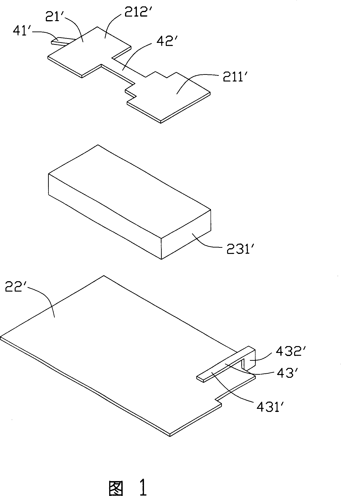
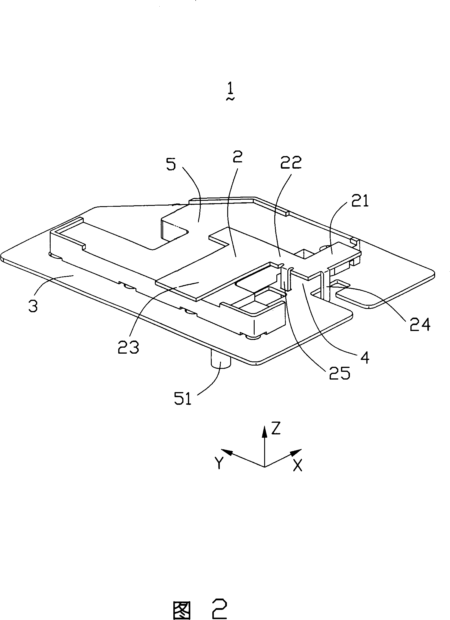
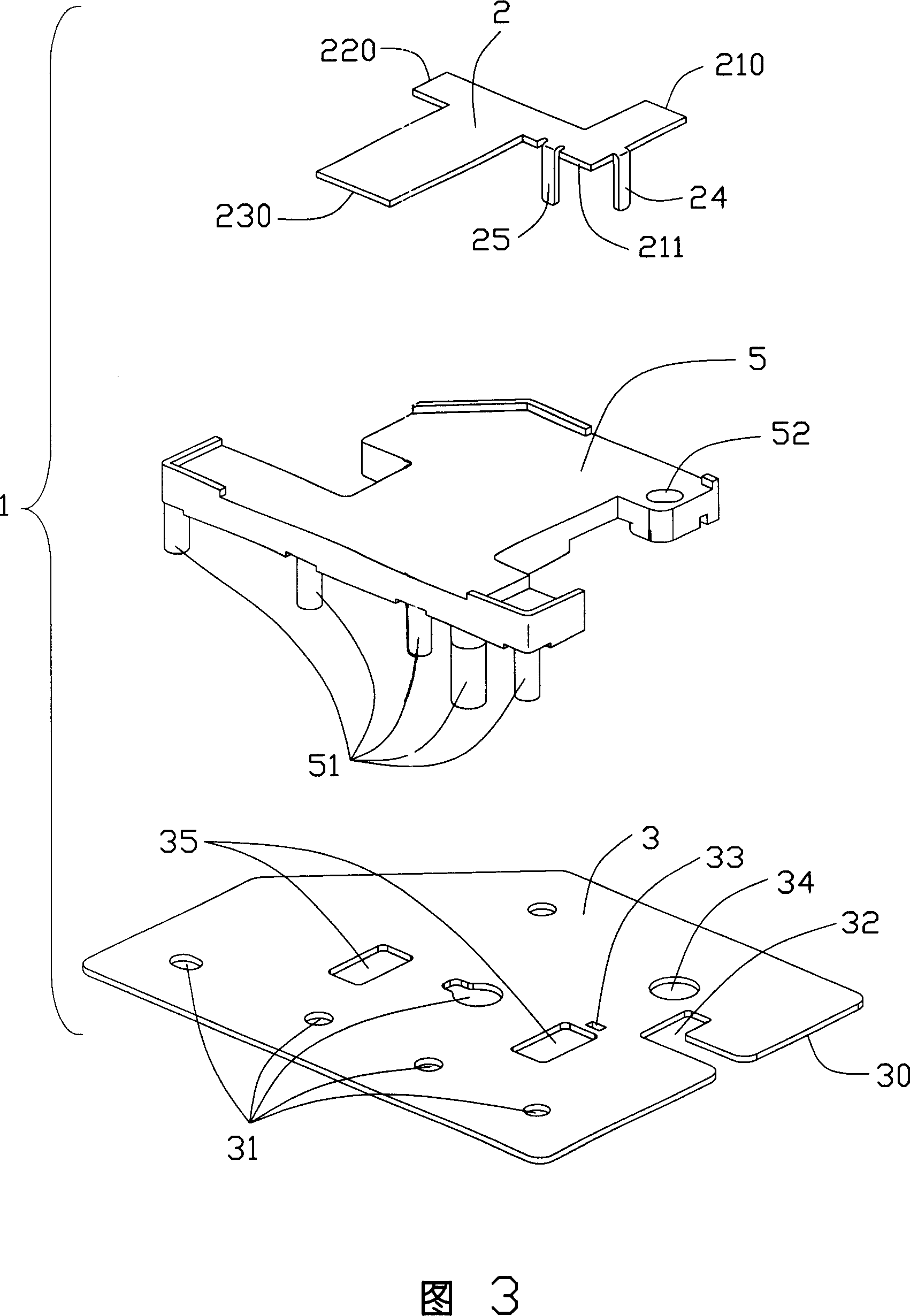
[0009] 2 and 3 show a preferred embodiment of the multi-frequency antenna 1 of the present invention. The multi-frequency antenna 1 includes a metal radiating plate 2 and a grounding plate 3 , wherein the radiating plate 2 is roughly in the shape of a “Z” and includes first, second and third rectangular metal sheets 21 , 22 , 23 . Wherein the first metal sheet 21 extends from the starting end 211 to the end 210 along the positive axis direction, the second metal sheet 22 extends from the starting end 211 of the first metal sheet 21 to the end 220 along the Y-axis positive direction, and the third metal sheet 23 extends from the The radiation plate 2 extends to the end 230 along the negative axis direction at a certain distance from the end 220 . The first metal sheet 21 extends down a first conductive sheet 24 at a certain distance from the starting end 211 , and a second conductive sheet 25 extends downward at a certain distance from the second metal sheet 22 to the end 220 a...


PUM


Abstract

The invention is concerned with the multi-frequency antenna, includes the radial lamella, the ground plate parallel distance with the radial lamella, the resonant cavity and the two conductive chip allocate in between the space of the radial lamella and the ground plate; the radial lamella is in 'Z' shape with the first metal chip and the second metal chip expanding to different direction where the first conductive chip expending downwards from the side of the first metal chip as the feed-in terminal, and the second conductive chip expending downwards from the side of the second metal chip to connect with the ground plate electrically as the grounding terminal, and the first metal chip expending of the side of the first conductive chip connecting with the second metal chip of the side of the second conductive chip.

Description

【Technical field】 [0001] The invention relates to a multi-frequency antenna, in particular to a small flat-panel antenna. 【Background technique】 [0002] In modern electronic equipment, the use of wireless communication technology for wireless transmission of data, sound, images, etc. has been more and more used. Antenna, as a component used to induce electromagnetic waves, is a necessary device for the application of wireless communication technology equipment. The early antennas were mostly installed outside the electronic equipment, mainly monopole or helical antennas, which have the characteristics of relatively simple design and high gain coefficient, but these antennas are large in size and installed outside the electronic equipment, and they also require matching The connecting device makes the structure more complicated, and the antenna has a strong directivity. When using it, it is necessary to change the direction of the antenna from time to time to obtain a bette...

Claims


Application Information

Patent Timeline
Patent Type & Authority Applications(China)
IPC IPC(8): H01Q1/36H01Q5/01H01Q13/00H01Q5/10
Inventor 柯云龙洪振达戴隆盛黄耀先谷柏冈
Owner FOXCONN (KUNSHAN) COMPUTER CONNECTOR CO LTD
Why Eureka
Try Eureka