EGR device
A technology of EGR valve and EGR cooler, which is applied in the direction of charging system, adding non-fuel substances to fuel, internal combustion piston engine, etc., can solve problems such as poor work and difficult cooling of EGR gas, and achieve the effect of preventing thermal deterioration
- Summary
- Abstract
- Description
- Claims
- Application Information
AI Technical Summary
Problems solved by technology
Method used
Image
Examples
Embodiment 1
[0031] A preferred embodiment of the present invention will be described in detail below with reference to the accompanying drawings.
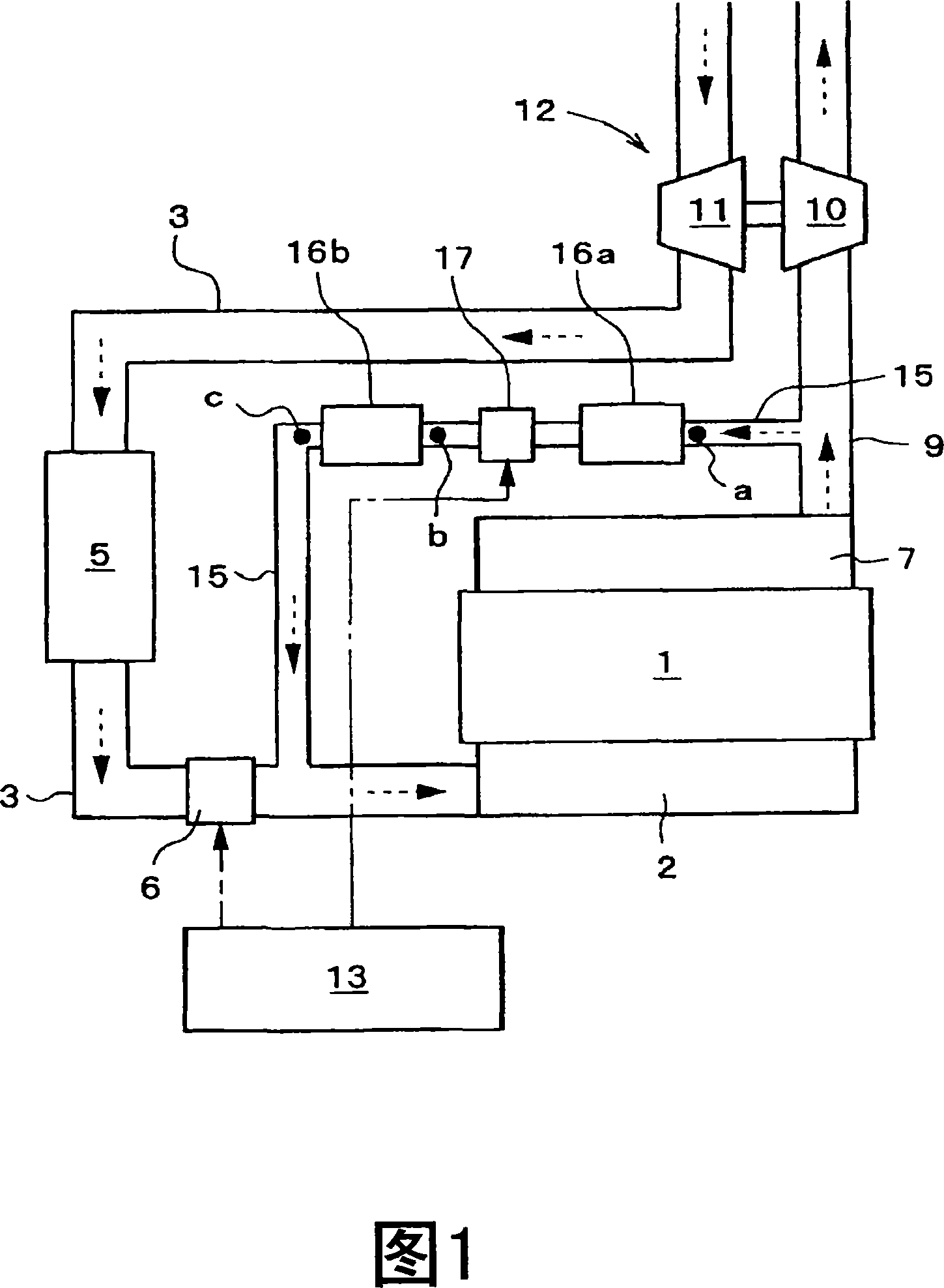
[0032] FIG. 1 is a schematic diagram of an EGR device according to the present embodiment.
[0033] The EGR device of the present embodiment is applicable to a diesel engine, and the diesel engine has: an engine 1; an intake passage 3 connected to the engine 1 through an intake manifold 2; an intercooler 5 arranged on the intake passage 3; The downstream side of the device 5 is arranged on the throttle valve (throttle) 6 on the intake passage 3; the exhaust passage 9 connected to the engine 1 through the exhaust manifold 7; A turbine (turbine) 10 on 9 and a compressor 11 arranged on the intake passage 3; a controller 13 for electronically controlling various devices such as the throttle valve 6 and the like.
[0034] The EGR device has: an EGR passage 15 communicating with the exhaust passage 9 on the upstream side of the turbine 10 and the i...
Embodiment 2
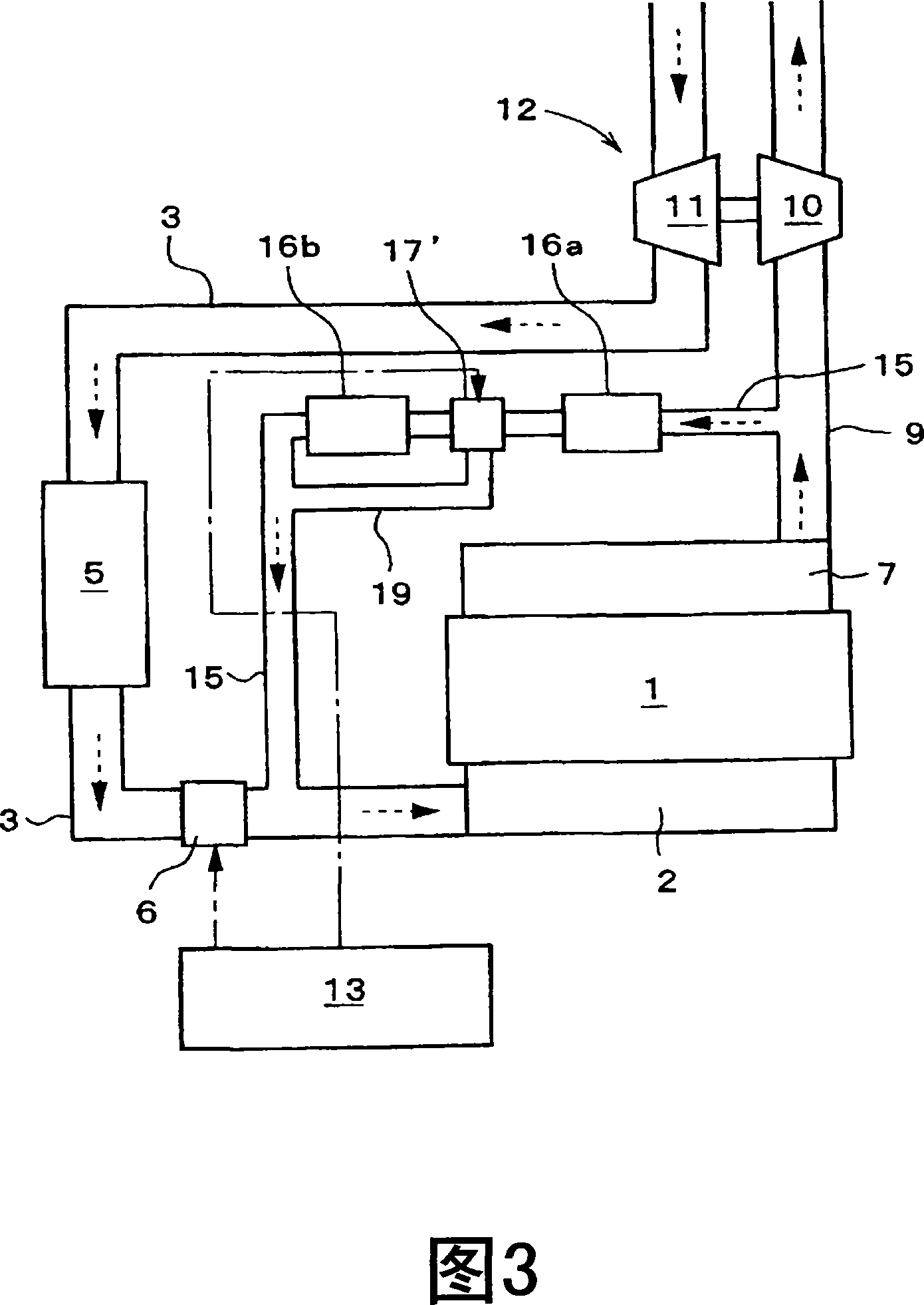
[0053] Next, another embodiment will be described using FIG. 3 .
[0054] The basic structure of this embodiment is the same as that shown in FIG. 1 , and the same reference numerals are assigned to the same constituent elements as in FIG. 1 , and description thereof will be omitted, and only differences will be described.
[0055] This embodiment is characterized in that a bypass passage 19 is provided in the EGR passage 15, which communicates the installation position of the EGR valve 17' and the EGR cooler 16b (second cooler) downstream of the EGR valve 17'. As the EGR valve 17', the exhaust gas flowing into the EGR valve 17' can be selectively flowed into either the EGR passage 15 on the downstream side or the bypass passage 19, and a directional switching valve that can adjust its flow rate is used. .
[0056] In this embodiment, the controller 13 switches the EGR valve 17 ′ so that the EGR gas that has passed through the first cooler 16 a flows into the bypass passage 1...
PUM
 Abstract
Description
Claims
Application Information
 - R&D
- Intellectual Property
- Life Sciences
- Materials
- Tech Scout
- Unparalleled Data Quality
- Higher Quality Content
- 60% Fewer Hallucinations
Browse by: Latest US Patents, China's latest patents, Technical Efficacy Thesaurus, Application Domain, Technology Topic, Popular Technical Reports.
© 2025 PatSnap. All rights reserved.Legal|Privacy policy|Modern Slavery Act Transparency Statement|Sitemap|About US| Contact US: help@patsnap.com


