
Process for producing liquid crystal display device, spacer particle dispersion liquid, and liquid crystal display device

A technology of liquid crystal display devices and spacer particles, which is applied in nonlinear optics, instruments, optics, etc., can solve the problems of spacer particles that are difficult to fix, contain impurities, and have poor dispersion, and achieve the effect of improving configuration accuracy and good wetting

Inactive Publication Date: 2008-01-09
SEKISUI CHEM CO LTD
View PDF10 Cites 11 Cited by
  • Summary
  • Abstract
  • Description
  • Claims
  • Application Information

AI Technical Summary

Problems solved by technology

However, the spacer particle dispersion sprayed onto the substrate may contain impurities, and the liquid crystal or alignment film may be contaminated by impurities.
In addition, when the dispersibility of the spacer particles in the spacer particle dispersion is poor, or the spacer particle dispersion contains impurities, the spacer particles are difficult to be fixed on the substrate during the drying process of the liquid droplets ejected on the substrate, so that There is a case where spacer particles cannot be placed under the shading area
[0016] Thus, in the conventional method of manufacturing a liquid crystal display device, the display quality such as color tone and contrast of the manufactured liquid crystal display device cannot be sufficiently improved.

Method used


Image

  • Process for producing liquid crystal display device, spacer particle dispersion liquid, and liquid crystal display device
  • Process for producing liquid crystal display device, spacer particle dispersion liquid, and liquid crystal display device
  • Process for producing liquid crystal display device, spacer particle dispersion liquid, and liquid crystal display device

Examples


Embodiment 1~13、 comparative example 1~3

[0297] (Preparation of spacer particle dispersion)

[0298] Take a necessary amount of spacer particles obtained by the method described above to reach a predetermined particle concentration, slowly add them to the solvent of the composition listed in Table 1 below, and stir sufficiently while using a sonicator, Spread it out. Thereafter, aggregates were removed by filtration through a stainless steel mesh having a mesh size of 10 μm, and spacer particle dispersions S1 to S8 were obtained. The surface tension of the obtained spacer particle dispersion was measured by the Wilhelmy method using a platinum plate. The results are shown in Table 1 below.

[0299] (production of substrate)

[0300] As the first substrate for the liquid crystal test panel, a color filter substrate was used, and as the second substrate, a liquid crystal display device substrate (TFT array dummy substrate) imitating the steps on the TFT array substrate was used.

[0301] (color filter substrate)

...

Embodiment 14~36

[0345] (Examples 14-36, Comparative Examples 4-14)

[0346] (Preparation of spacer particle dispersion)

[0347] Take the necessary amount of spacer particles obtained by the method to reach the specified particle concentration, slowly add to the solvent of the composition listed in the following Table 3 and Table 4, the same as in Example 1, etc., by adding It was dispersed while stirring well using a sonicator. Thereafter, aggregates were removed by filtration through a stainless steel mesh having a mesh size of 10 μm, and a spacer particle dispersion was obtained.

[0348] The surface tension at 20° C. of the obtained spacer particle dispersion was measured by the Wilhelmy method using a platinum plate. In addition, when the spacer particle dispersion liquid was introduced into a test tube with an inner diameter of φ5 mm until the height reached 10 cm and then left to stand, the time required for the accumulation of spacer particles at the bottom of the test tube could be...

Embodiment 37~46

[0398] (Examples 37-46, Comparative Examples 15-20)

[0399] (Preparation of spacer particle dispersion)

[0400] All the solvents used in the preparation of the spacer dispersion were grades used in the electronics industry. The preparation of the spacer particle dispersion was carried out in a clean room (Class 10000).

[0401] Take a necessary amount of spacer particles obtained by the method described above to reach a specified particle concentration, slowly add to the solvent of the composition listed in the following Tables 6 and 7, and fully Stir to disperse it. Thereafter, aggregates were removed by filtration through a stainless steel mesh having a mesh size of 10 μm, and a spacer particle dispersion was obtained.

[0402] Then, in Examples 37 to 46 shown in Table 6 below, the spacer particle dispersion was filtered with a filter having a filtration diameter through which the spacer particles could pass. Then, after centrifugation was performed to remove dust part...


PUM

PropertyMeasurementUnit
surface tensionaaaaaaaaaa

Abstract

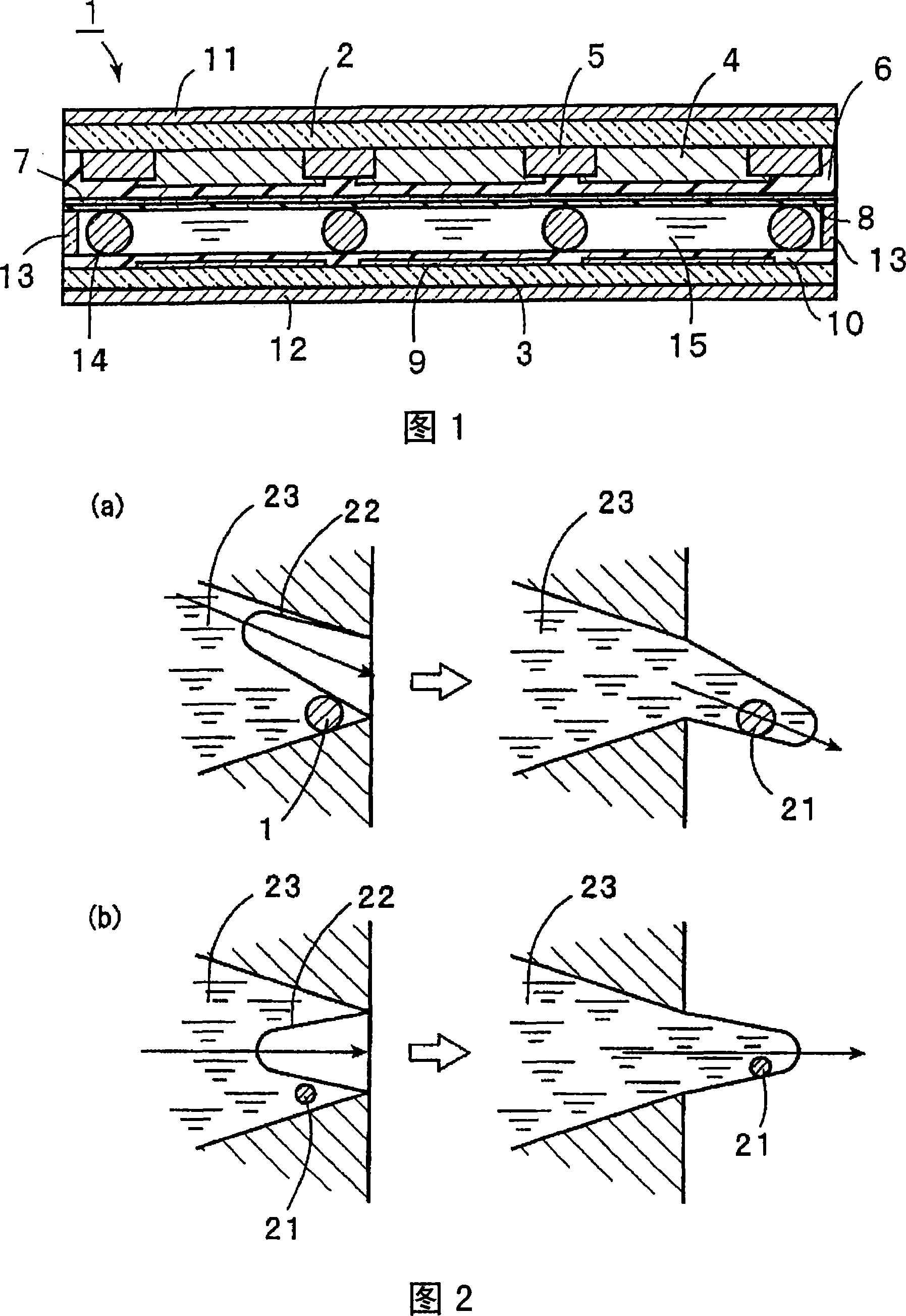
This invention provides a process for producing a liquid crystal display device that can dispose spacer particles at positions corresponding to a nonpixel region on a substrate through an improvement in a spacer particle dispersion liquid. The production process is a process for producing a liquid crystal display device having a pixel region and a nonpixel region and comprises the step of delivering a spacer particle dispersion liquid containing spacer particles (14) dispersed therein onto a surface of a first substrate (2) or a second substrate (3) with an ink jet device to place the spacer particles (14) at specific positions corresponding to the nonpixel region. In the step of disposing the spacer particles (14), the liquid contact part in an ink chamber containing the spacer particle dispersion liquid in a head of the ink jet device is formed of a hydrophilic material having a surface tension of not less than 31 mN / m, and the surface tension of the spacer particle dispersion liquid is not less than 33 mN / m and not more than a value of (surface tension of the liquid contact part + 2 mN / m).

Description

technical field [0001] The present invention relates to a method for manufacturing a liquid crystal display device having a step of arranging spacer particles on the surface of a substrate using an inkjet device, and in particular to a method for manufacturing a liquid crystal display device with an improved spacer particle dispersion, a spacer particle dispersion, and a liquid crystal display device . Background technique [0002] Liquid crystal display devices are widely used in personal computers, portable electronic devices, and the like. FIG. 9 is a schematic front sectional view showing an example of a conventional liquid crystal display device. In the liquid crystal display device 200, two transparent substrates 201, 201 are arranged to face each other. [0003] On the inner surface of the transparent substrate 201, a color filter 203 and a black matrix 204 are formed. A protective layer 205 is formed on the color filter 203 and the black matrix 204 . On the prote...

Claims


Application Information

Patent Timeline
Patent Type & Authority Applications(China)
IPC IPC(8): G02F1/1339G02F1/13
Inventor 上田伦久
Owner SEKISUI CHEM CO LTD
Learn More