Ophthalmologic apparatus

An ophthalmic device and fundus photography technology, applied in ophthalmoscope, medical science, equipment for testing eyes, etc., to achieve high-speed and high-precision tracking effect

Inactive Publication Date: 2008-01-16
KK TOPCON
View PDF1 Cites 24 Cited by
  • Summary
  • Abstract
  • Description
  • Claims
  • Application Information

AI Technical Summary

Problems solved by technology

[0009] However, in the technology disclosed in this patent document, in order to detect the line-of-sight direction of the subject's eye, it is necessary to project a detection beam f

Method used


Image

  • Ophthalmologic apparatus
  • Ophthalmologic apparatus
  • Ophthalmologic apparatus

Examples


Embodiment

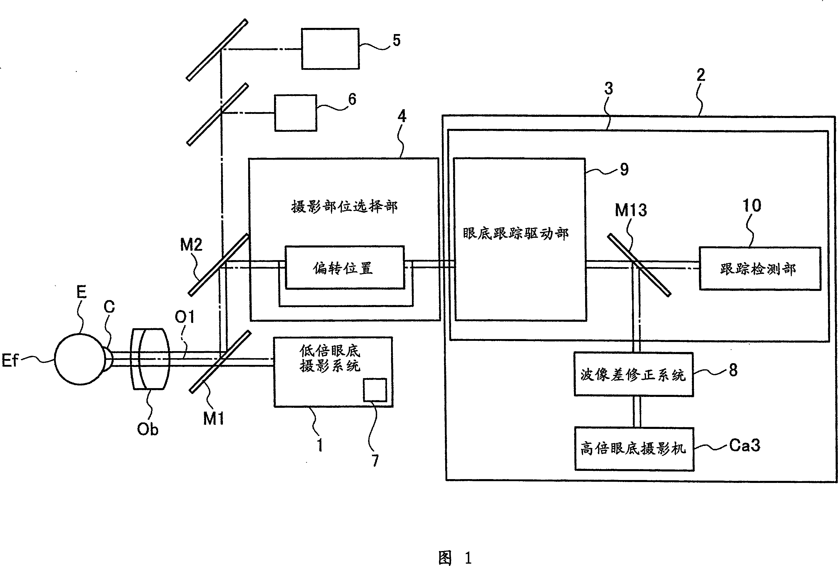
[0026] Fig. 1 is a block diagram showing the outline of the ophthalmic device of the present invention. The main body of the ophthalmic device roughly includes: a low-power fundus photography system 1 for observing the fundus Ef of the eye E to be inspected; a high-power fundus photography system 2 for photographing the fundus Ef of the eye to be inspected; and a high-power fundus photography system 2 for tracking the eye E to be inspected. The fundus tracking control unit 3 in the line of sight direction; and the imaging site selection unit 4 for selecting the imaging site.

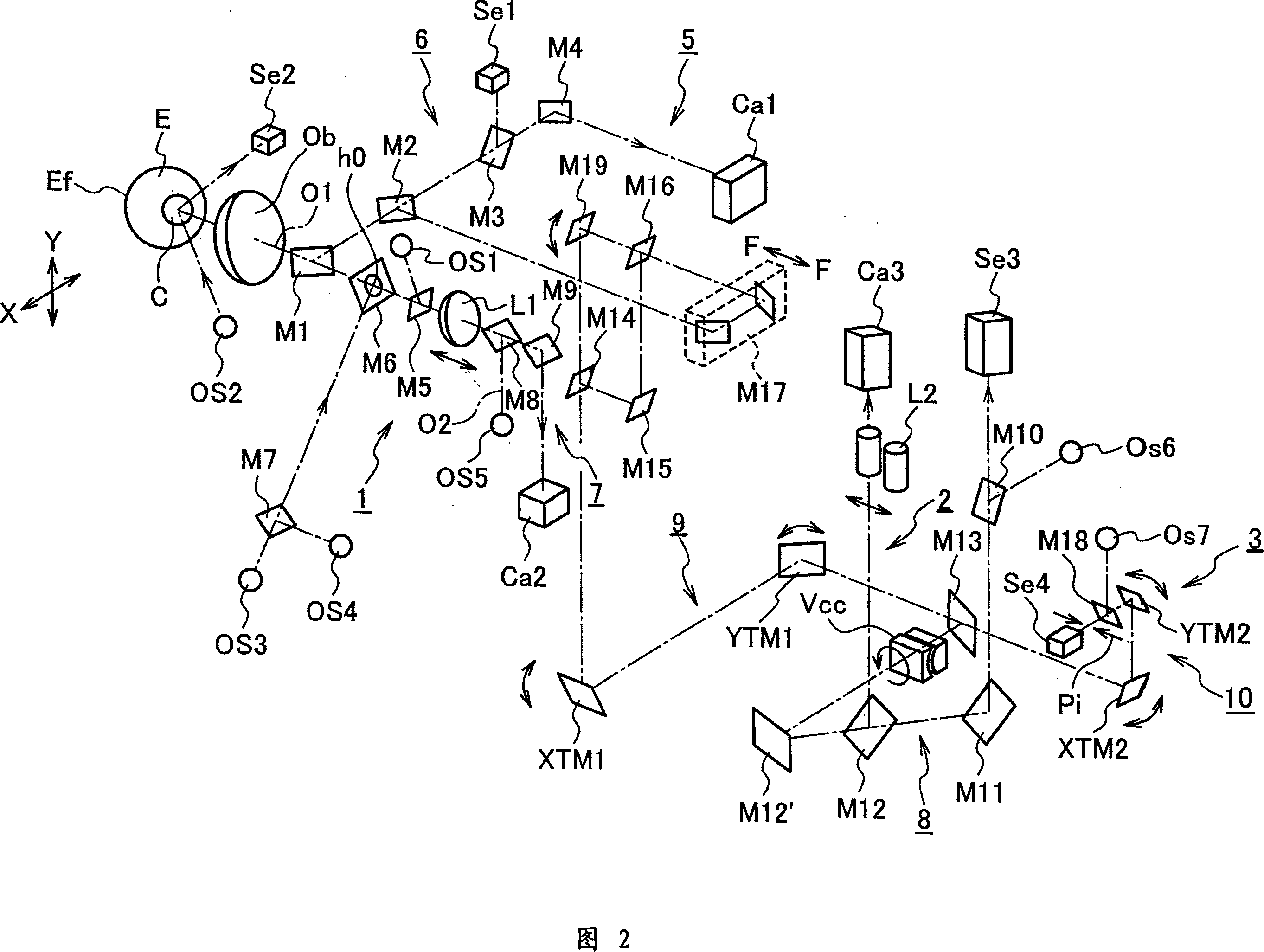
[0027] FIG. 2 is a detailed view of the optical system of the ophthalmic device shown in FIG. 1 . The optical system roughly includes a common objective lens Ob facing the front of the subject's eye E, a low-magnification fundus photography system 1, a high-power fundus photography system 2, an anterior eye observation system 5, an alignment detection system 6, and a fixation target projection system 7....


PUM

PropertyMeasurementUnit
Wavelengthaaaaaaaaaa

Abstract

An ophthalmologic apparatus is disclosed. In one aspect, the apparatus includes ocular fundus photographing systems for forming an ocular fundus image of the examined eye, based on a reflective beam from the ocular fundus of the examined eye, and a light receiving element for receiving the reflective beam reflected at a reflective region of an illumination region illuminated on the ocular fundus. The apparatus further may include a tracking detector having a scanning unit for detecting a gaze direction of the tested eye, and an ocular fundus tracking controller for tracking the ocular fundus photographing system to the gaze direction.

Description

technical field [0001] The present invention relates to an ophthalmic apparatus capable of photographing the fundus with high resolution, having a fundus tracking control unit that detects the direction of the line of sight of an eye to be inspected and makes a fundus imaging system track the direction of the line of sight. Background technique [0002] In the conventional general fundus camera, due to the optical aberration of the subject's eye, the captured fundus image is deteriorated, and there is a problem that a clear fundus image cannot be obtained at a high magnification. [0003] Therefore, recently, a technique of measuring the optical aberration of the subject's eye, correcting the optical aberration of the subject's eye using a compensation optical system based on the result, and capturing a fundus image has been proposed. With this technique, the influence of the optical aberration of the eye to be inspected can be eliminated, and a fundus image of higher magnif...

Claims


Application Information

Patent Timeline
IPC IPC(8): A61B3/14A61B3/12
CPCA61B3/102A61B3/113A61B3/12
Inventor 秀岛昌行布川和夫藤野诚岩阳一郎三轮珠美后藤义明竹内乐田边贵大
Owner KK TOPCON
Why Eureka
Try Eureka