Press die casting device and press die casting method

A pressurized casting and pressure-increasing technology, which is applied in the field of pressurized casting, can solve the problems of increasing pressurized pressure and inability to obtain quality casting products, etc.

Inactive Publication Date: 2008-01-16
MAZDA MOTOR CORP
View PDF1 Cites 8 Cited by
  • Summary
  • Abstract
  • Description
  • Claims
  • Application Information

AI Technical Summary

Problems solved by technology

[0004] But only increase the pressure step by step, in the low pressure state, especially near the surface of the mold cavity where the melt solidifies faster, the thinness of

Method used


Image

  • Press die casting device and press die casting method
  • Press die casting device and press die casting method
  • Press die casting device and press die casting method

Examples


experiment example

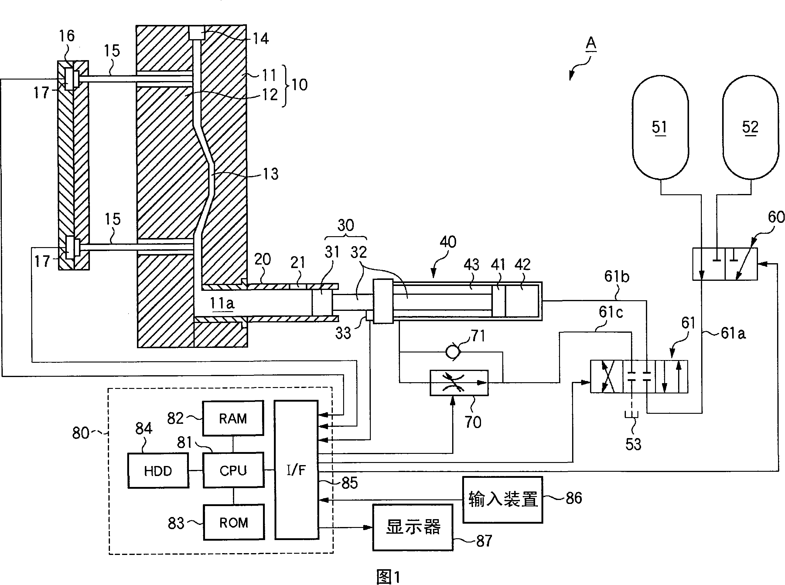
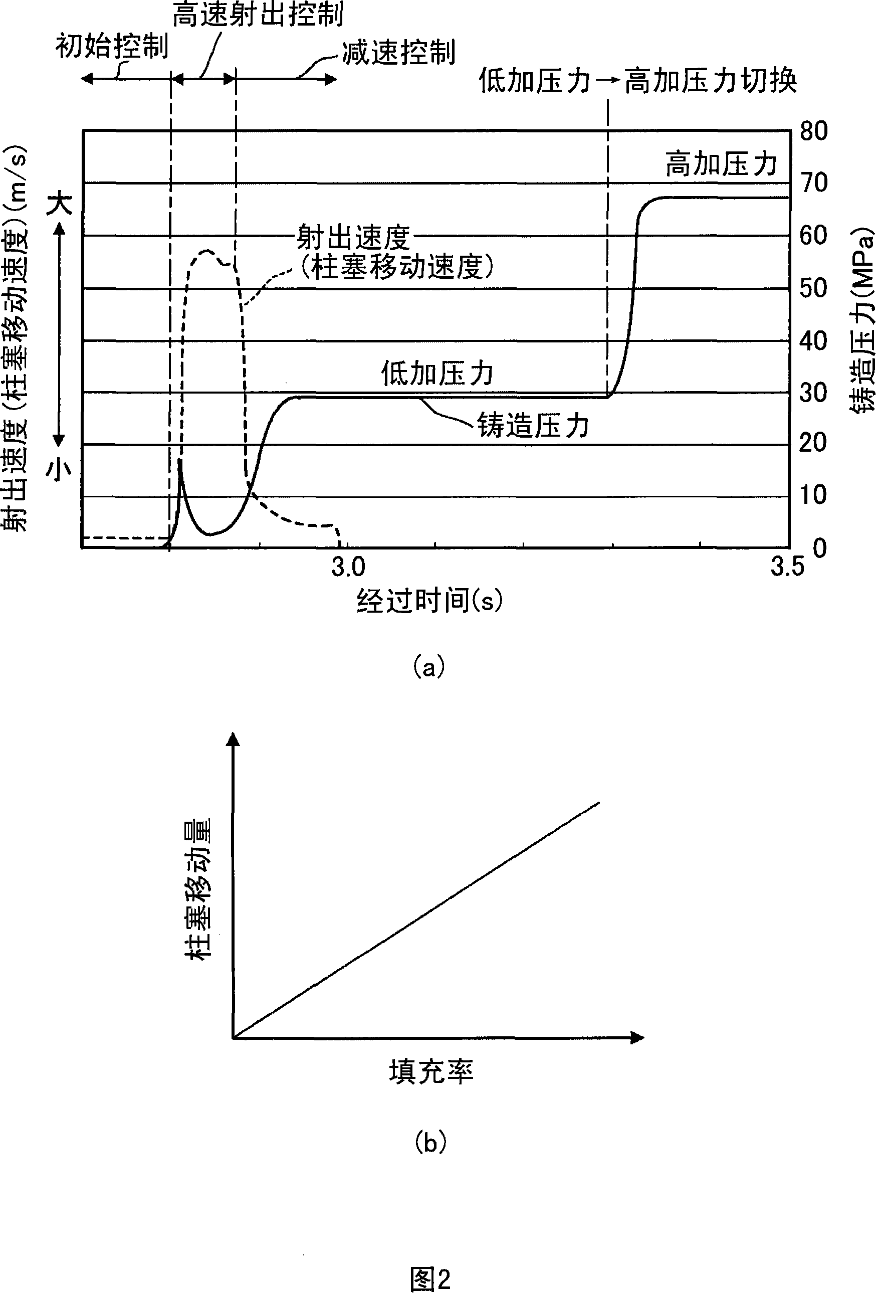
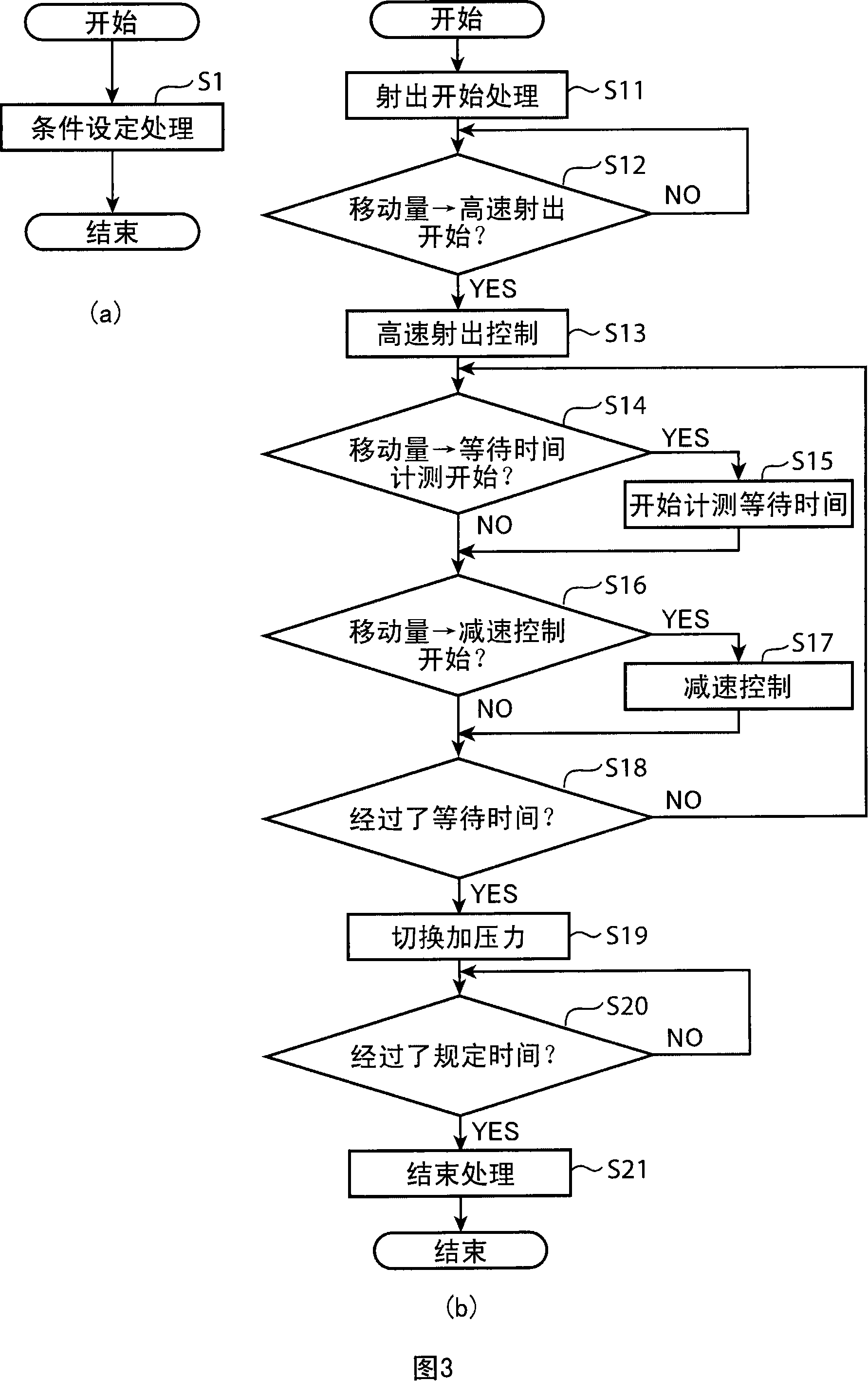
[0059] Casting roughness was investigated in the case of changing the filling rate at the timing of switching from high-speed injection control to deceleration control, and increasing the pressure after filling the melt in one step and in two steps. The amount of mouth and the incidence of trachoma. The casting object is the cylinder block of the engine, and the melt is aluminum alloy melt. The pressurization pressure after filling the molten metal is about 70MPa in one stage, about 30MPa in the first stage and about 70MPa in the second stage in two stages. When the pressurization pressure after filling the melt is increased in two stages, the timing of switching the pressurization pressure is 0.45 seconds after the measurement from the time when the fill rate of the melt reaches 92%.

[0060] Fig. 4 is a schematic diagram showing experimental results. Fig. 4(a) shows the relationship between the amount of casting burrs and the filling rate as the timing for switching from hi...


PUM


Abstract

The present invention relates to a pressure casting device, by means of ejaculating solution with high speed, to ensure the filling ratio of the molten to reach the prescribed filling ratio selected from the range of 90 percent to 98 percent relative to the filling ratio of the mould cavity, then to implement deceleration control of a plunger piston and increase the pressure of the melted step by step.

Description

technical field [0001] The present invention relates to a pressurized casting technique for pressurizing molten liquid after filling the molten liquid. Background technique [0002] In a casting method in which molten metal is injected and filled into a cavity of a mold, blow holes may occur in a cast product as the molten metal in the cavity solidifies and shrinks. The pressure casting method is to pressurize the molten liquid in the cavity after filling the molten liquid, thereby preventing the occurrence of blisters. In order to effectively prevent sand holes, increasing the pressure relative to the melt is an effective method. However, if the pressure applied to the molten metal is increased, the molten metal enters the separation surface of the mold, etc., causing the problem of increasing the burrs of the cast product. In addition, because the mold is exposed to high pressure, it is easier to damage it and shorten its service life. [0003] Japanese Patent Laid-Open...

Claims


Application Information

Patent Timeline
IPC IPC(8): B22D17/32
Inventor 古谷幸儿藤田智浩上东喜纪
Owner MAZDA MOTOR CORP
Why Eureka
Try Eureka