
Device and method for filling tanks

a technology for filling tanks and devices, applied in the direction of gas/liquid distribution and storage, vessel construction details, electrochemical generators, etc., can solve the problems of not allowing the filling to be adapted, increasing the cost and complexity of installation, and demanding the pre-cooling of hydrogen prior to filling

Active Publication Date: 2021-01-07
LAIR LIQUIDE SA POUR LETUDE & LEXPLOITATION DES PROCEDES GEORGES CLAUDE
View PDF0 Cites 1 Cited by
  • Summary
  • Abstract
  • Description
  • Claims
  • Application Information

AI Technical Summary

Benefits of technology

The patent describes a controller that can regulate the flow rate and pressure of gas transferred through a tank. It does this by measuring the temperature of the gas and calculating the average temperature of the gas transferred through each end of the tank. By controlling these factors, the controller can increase the rate of filling a tank when the temperature drops and decrease the rate of filling when the temperature rises. This allows for better control over the tank's filling process.

Problems solved by technology

In addition, this pre-cooling of the hydrogen prior to filling is very demanding.
For high-capacity service stations, this cooling system increases the cost and the complexity of the installation.
This design does not allow the filling to be adapted to suit different tanks which may for example have different structural characteristics and / or different starting pressures.

Method used


Image

  • Device and method for filling tanks
  • Device and method for filling tanks
  • Device and method for filling tanks

Examples


Embodiment Construction

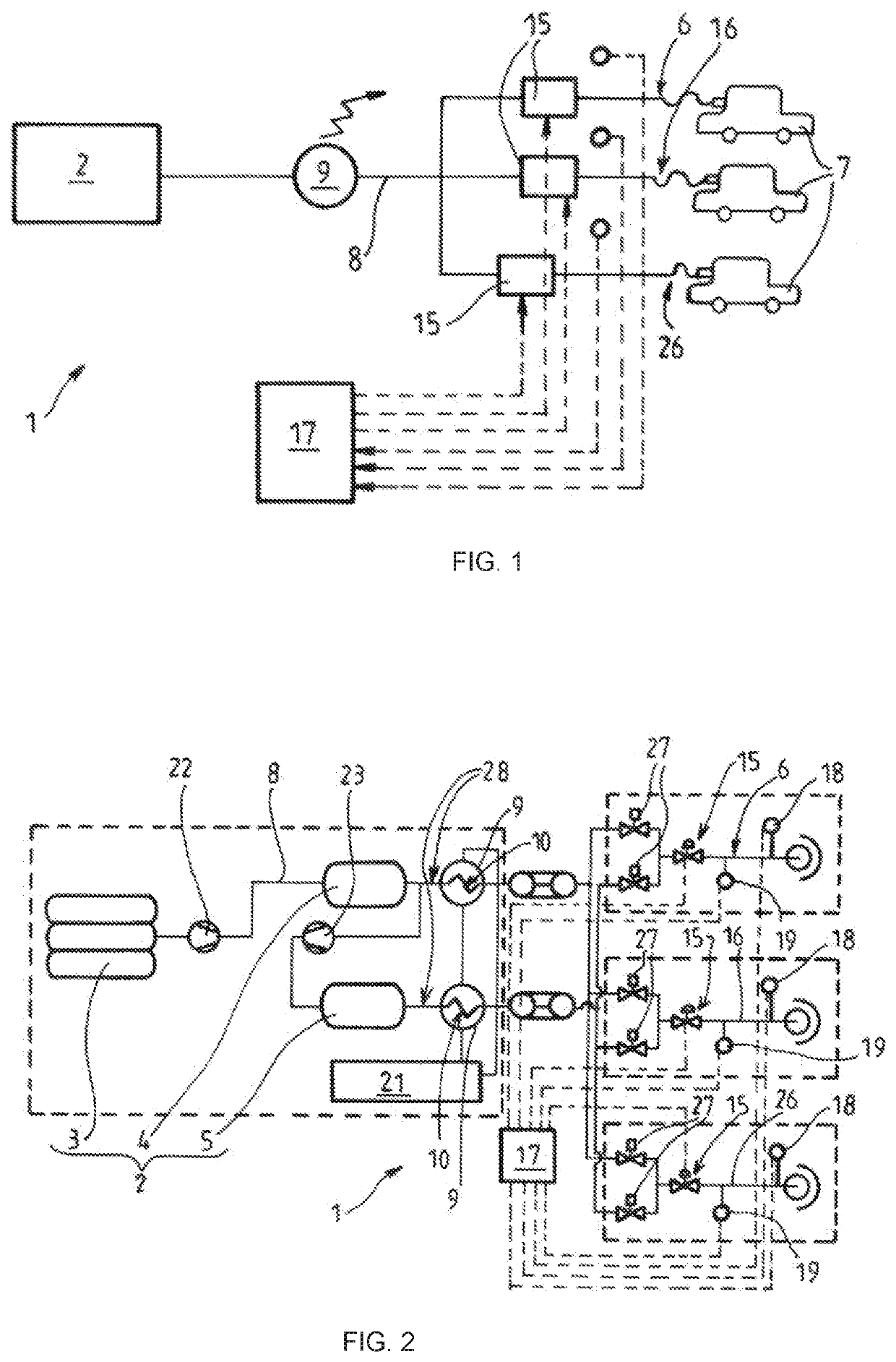
[0038]The pressurized-gas tank filling device 1 depicted schematically in [FIG. 1] may notably be a filling station for filling vehicle hydrogen tanks 7.

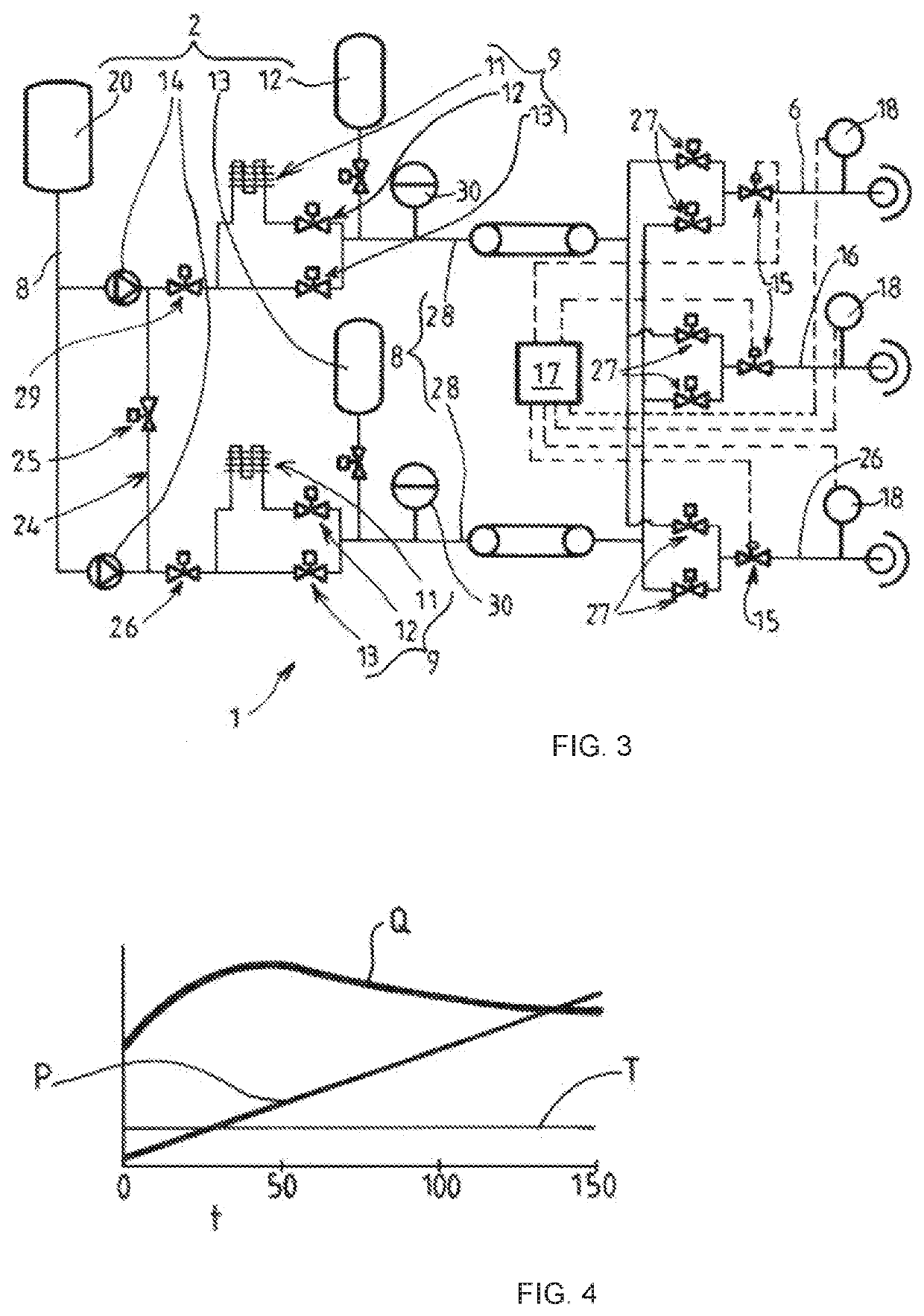
[0039]This device conventionally comprises a fluid transfer circuit 8 equipped with an upstream end connected to at least one source 2 of pressurized gas (preferably at least two sources) and at least two parallel downstream ends 6, 16, 26 which are intended to be connected to distinct tanks 7 that are to be filled (distribution hoses fitted with nozzle guns or equivalent for example).

[0040]The transfer circuit 8 comprises a temperature regulating member 9 for regulating the temperature of the gas transferred from the source 2 towards the downstream end or ends. This temperature regulating member 9 is designed in particular to bring the gas transferred to a determined temperature as detailed hereinafter. In particular, the regulating member 9 may be configured in such a way as to cool the gas from the source 2 (when the gas from the...


PUM


Abstract

Device and method for filling pressurized-gas tanks, comprising a fluid transfer circuit provided with an upstream end intended to be connected to a source of gas and at least two parallel downstream ends intended to be connected to distinct tanks that are to be filled, the transfer circuit comprising a temperature regulating member for regulating the temperature of the gas transferred from the source towards the downstream ends, the gas temperature regulating member being positioned in the transfer circuit upstream of the at least two downstream ends, which means to say that the gas temperature regulating member is common to the at least two downstream ends, characterized in that the at least two downstream ends of the circuit each comprise a respective control member for controlling the flow rate and / or the pressure of the transferred gas and configured to control the flow rate and / or the pressure in each of the downstream ends independently.

Description

CROSS-REFERENCE TO RELATED APPLICATIONS[0001]This application claims the benefit of priority under 35 U.S.C. § 119 (a) and (b) to French patent application No. FR 1 907 365, filed Jul. 3, 2019, the entire contents of which are incorporated herein by reference.BACKGROUNDField of the Invention[0002]The invention relates to a device and a method for filling tanks.[0003]The invention relates more particularly to a device for filling pressurized-gas tanks, particularly vehicle hydrogen tanks, comprising a fluid transfer circuit provided with an upstream end intended to be connected to a source of gas and at least two parallel downstream ends intended to be connected to distinct tanks that are to be filled, the transfer circuit comprising a temperature regulating member for regulating the temperature of the gas transferred from the source towards the downstream ends, the gas temperature regulating member being positioned in the transfer circuit upstream of the at least two downstream ends...

Claims


Application Information

Patent Timeline
IPC IPC(8): F17C5/00F17C5/06F17C13/02
CPCF17C5/007F17C5/06F17C13/025F17C2223/036F17C2205/0382F17C2221/012F17C2205/0323F17C13/04F17C13/026F17C13/02F17C13/00F17C2223/0123F17C2250/0439F17C2270/0168F17C2227/0306F17C2225/0123F17C2205/0338F17C2227/0135F17C2205/0376F17C2223/0161F17C2223/033F17C2250/043F17C2225/036F17C2205/0326F17C2250/0631F17C2250/0443F17C2250/0636F17C2205/0142F17C2227/0388F17C2250/032F17C2227/0157F17C2227/0355F17C2250/01F17C2227/04F17C2250/0626F17C2205/0364F17C2260/023F17C2265/065F17C2270/0184F17C2227/0185F17C2227/043Y02E60/32F17C5/02F17C2201/054F17C2270/0178
Inventor THIEU, ANH THAODEBESOMBES, LOUISFAIRY, VINCENT
Owner LAIR LIQUIDE SA POUR LETUDE & LEXPLOITATION DES PROCEDES GEORGES CLAUDE
Learn More