Wide bandwidth, low loss photonic bandgap fibers

a photonic bandgap fiber and wide bandwidth technology, applied in the field of optical fibers, can solve problems such as difficulty in increasing the transmission window, and achieve the effect of improving the air filling fraction and low loss

Inactive Publication Date: 2010-09-30
IMRA AMERICA
View PDF3 Cites 25 Cited by
  • Summary
  • Abstract
  • Description
  • Claims
  • Application Information

AI Technical Summary

Benefits of technology

[0009]Various embodiments include hollow core (HC) photonic bandgap fibers (PBGFs) with a square lattice (SQL) configured with a wide transmission window and low loss. Various embodiments described herein include fibers that are fabricated with core and cladding pressure control that improves the air filling fraction. In at least some embodiments, a relative transmission window of at least about 35% (Δλ / λc=0.35) is obtained, and up to about 65% can be obtained, when Δλ is measured by the width of the transmission curve at approximately 10% of the maximum intensity. Some embodiments describe a SQL photonic bandgap fiber with relative bandgap beyond 40%.

Problems solved by technology

The conventional PBGF cladding structure with a hexagonal lattice has limited bandgap which may make it difficult to increase its transmission window.

Method used


Image

  • Wide bandwidth, low loss photonic bandgap fibers
  • Wide bandwidth, low loss photonic bandgap fibers
  • Wide bandwidth, low loss photonic bandgap fibers

Examples


example i

Fabricated HC PBGF with Rectangular Lattice

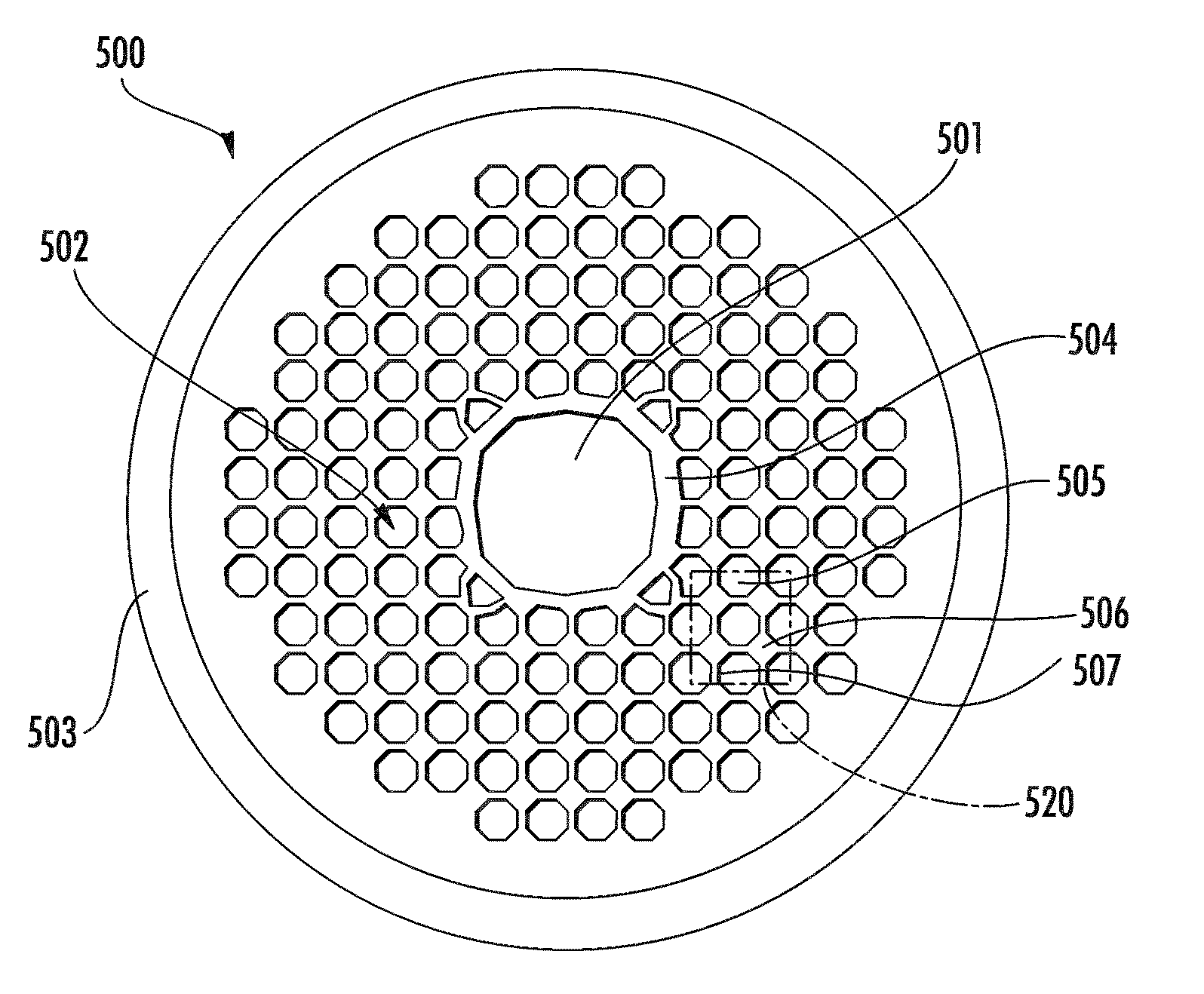
[0078]In the example described below, a HC SQL PBGF was fabricated with fiber outer diameter of 125 μm. FIG. 9A illustrates an image of a fabricated preform 900. Features 901-905 of fabricated preform 900 correspond with 501-507 of cane 500, and eventually with 301-307 of fiber 300. FIG. 9B illustrates an exploded region of a portion of the image of FIG. 9A and shows a unit cell of preform 900. FIG. 9C is a scanning electron microscope (SEM) image illustrating a cross-sectional view of a fabricated SQL PBGF drawn using the preform of FIG. 9A. The irregularities in FIG. 9C are believed to be by-products of the cleaving process for preparing fiber end for the photos, and not defects in the PBG fiber structure. Air-filling fraction is estimated to be larger than 83% in this example. FIG. 9D is a SEM image illustrating an exploded view of the fiber illustrated in FIG. 9C, and illustrates the cladding structure of the fabricated fiber. As illust...


PUM

PropertyMeasurementUnit
aspect ratioaaaaaaaaaa
outer diameteraaaaaaaaaa
inner diameteraaaaaaaaaa

Abstract

Various embodiments described herein comprise hollow core (HC) photonic bandgap fibers (PBGF) with a square lattice (SQL). In various embodiments the, HC SQL PBGF includes a cladding region comprising 2-10 layers of air-holes. In various embodiments, the HC SQL PBGF can be configured to provide a relative wavelength transmission window Δλ/λc larger than about 0.35 and minimum transmission loss in a range from about 70 dB/km to about 0.1 dB/km. In some embodiments, the HC SQL PBGF fiber can be a polarization maintaining fiber. Methods of fabricating such fibers are also disclosed herein along with some examples of fabricated fibers. Various applications of such fibers are also described herein.

Description

CROSS-REFERENCE TO RELATED APPLICATIONS[0001]This application claims the benefit under 35 U.S.C. §119(e) of U.S. Provisional Application No. 61 / 165,328, titled “WIDE BANDWIDTH, LOW LOSS PHOTONIC BANDGAP FIBERS,” filed on Mar. 31, 2009 which is hereby incorporated by reference herein in its entirety.[0002]This application is also related to U.S. Pat. No. 7,209,619, entitled “Photonic Bandgap Fibers” filed on Dec. 30, 2005 (IMRAA.032A), and U.S. Pat. No. 7,418,836, filed on Mar. 15, 2007, entitled “Photonic Bandgap Fibers” (IMRAA.032DV1), each of which is hereby incorporated by reference herein in its entirety.BACKGROUND OF THE INVENTION[0003]1. Field of the Invention[0004]This application relates to optical fibers in general and to photonic bandgap fibers in particular. Some aspects of this application are directed towards a photonic bandgap fiber having increased transmission bandwidth.[0005]2. Description of the Related Art[0006]Hollow core (HC) photonic bandgap fibers (PBGF) can b...

Claims


Application Information

Patent Timeline
Patent Type & Authority Applications(United States)
IPC IPC(8): G02B6/02B29D11/00
CPCB29D11/00663G02B6/024G02B6/02347G02B6/02328
Inventor DONG, LIANGTHOMAS, BRIAN K.SUZUKI, SHIGERUFU, LIBIN
Owner IMRA AMERICA
Why Eureka
Try Eureka