Pneumatic driving device

A technology of drivers and air-filled holes, which is applied in the direction of fluid pressure actuators, manipulators, manufacturing tools, etc., can solve the problems of complex manufacturing process, poor rigidity, and poor durability, and achieve the effect of simple manufacturing process, high rigidity, and good elasticity

Inactive Publication Date: 2008-01-16
ZHEJIANG UNIV OF TECH
View PDF1 Cites 7 Cited by
  • Summary
  • Abstract
  • Description
  • Claims
  • Application Information

AI Technical Summary

Problems solved by technology

[0003] In order to solve the deficiencies in the prior art of the pneumatic flexible actuator with complex manufacturing process, poor durability, and poor rigidity, the present invention provides a pneumatic actuator with simpler manufacturing process, durability, and better rigidity

Method used


Image

  • Pneumatic driving device

Examples


Embodiment Construction

[0011] The present invention will be further described below in conjunction with the accompanying drawings.

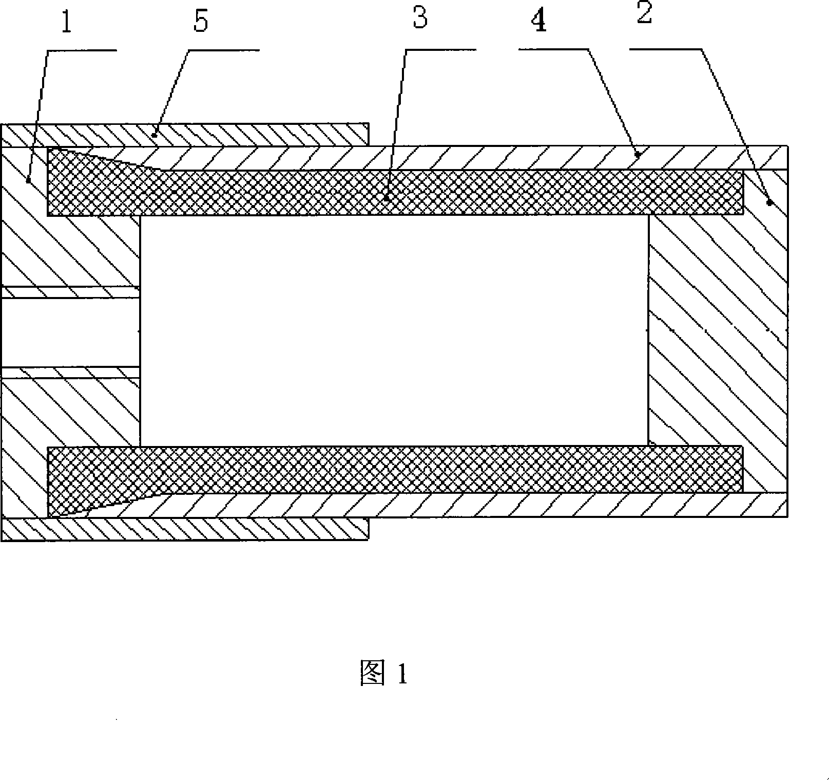
[0012] Referring to the accompanying drawings: a pneumatic driver, including a left end cover 1, a right end cover 2, the left end cover 1 is provided with an air-filled hole, and the two ends of the rubber tube 3 are respectively sealed and connected with the left end cover 1 and the right end cover 2, and it is characterized in that: The outer side of the right end cover 2 is fixedly connected with the rigid inner bushing 4, the inner bushing 4 is sleeved outside the rubber tube 3, and the inner bushing 4 is slidably attached to the outer wall of the rubber tube 3; the left end cover 1 The outer side of the outer bushing 5 is fixedly connected with the rigid outer bushing 5, and the outer bushing 5 is sleeved outside the inner bushing 4, and the outer bushing 5 is slidably attached to the outer wall of the inner bushing 4.

[0013] The free end of the inner bushing 4...


PUM


Abstract

Disclosed is an aerodynamic driver, comprising a left end cover and a right end cover, wherein an inflation hole is arranged on the left end cover and the two ends of a rubber tube are respectively in sealed connection with the left end cover and the right end cover. The invention is characterized in that the outer side of the right end cover is fixedly connected with a rigid inner neck bush, which is nested on the outside of the rubber tube and can be clung glidingly on the outer wall of the rubble tube; the outer side of the left end cover is fixedly connected with a rigid outer neck bush, which is nested on the outside of the inner neck bush and can be clung glidingly on the outer wall of the inner neck bush.

Description

(1) Technical field [0001] The invention belongs to a driver, in particular to a pneumatic driver, which is suitable for designing and manufacturing multi-fingered dexterous hands. (2) Technical background [0002] Efficient and flexible drives are the basis and prerequisite for the design of robotic multi-fingered dexterous hands. Traditional robotic multi-fingered dexterous hands mostly use motors as drives, and their structural size is large, making it difficult to miniaturize multi-fingered dexterous hands. Pneumatic joints are also proposed, such as invention patent No. 200510049589.5, the patent name is an invention patent of a flexible actuator, which discloses a pneumatic flexible actuator, which consists of a left end cover, a rubber tube, a spring nested in the rubber tube wall, a right end cover, Composed of pipe joints, the invention also has the following disadvantages: 1. The spring is nested in the rubber tube, the manufacturing process is complicated and the ...

Claims


Application Information

Patent Timeline
Patent Type & Authority Applications(China)
IPC IPC(8): B25J19/00B25J13/00F15B15/00
Inventor 张立彬钱少明杨庆华高峰鲍官军
Owner ZHEJIANG UNIV OF TECH
Why Eureka
Try Eureka