Cross cramp for steel wire

A cross buckle and wire rope technology, applied in the direction of transmission elements or pulley ropes or cables, protective equipment, textile cables, etc., can solve problems such as wire rope damage, and achieve the effects of easy protection, low processing cost, and material saving

Active Publication Date: 2008-01-16
布鲁克(苏州)工程有限公司
View PDF1 Cites 5 Cited by
  • Summary
  • Abstract
  • Description
  • Claims
  • Application Information

AI Technical Summary

Problems solved by technology

[0003] In order to overcome the disadvantage that the existing steel wire rope cross buckle is easy to cause damage to the steel wire rope,

Method used


Image

  • Cross cramp for steel wire
  • Cross cramp for steel wire
  • Cross cramp for steel wire

Examples


Example Embodiment

[0021] Example one:

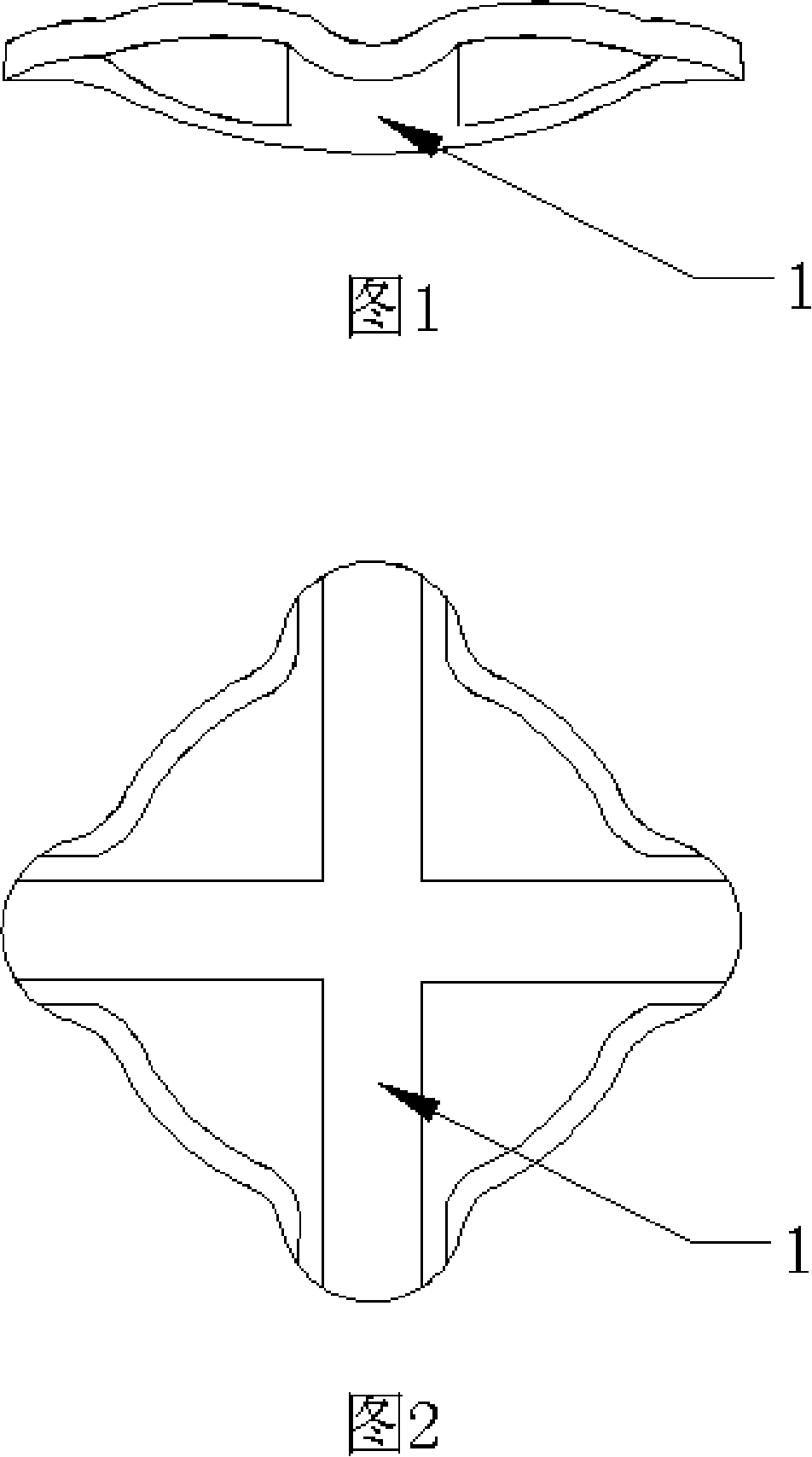
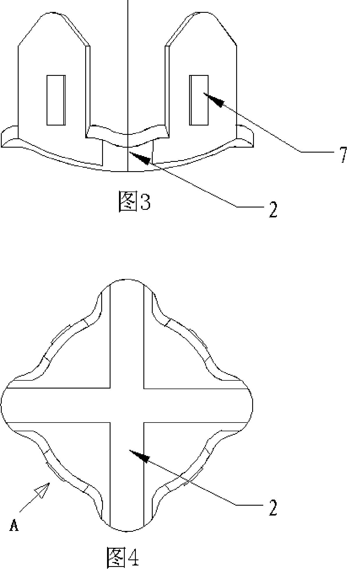
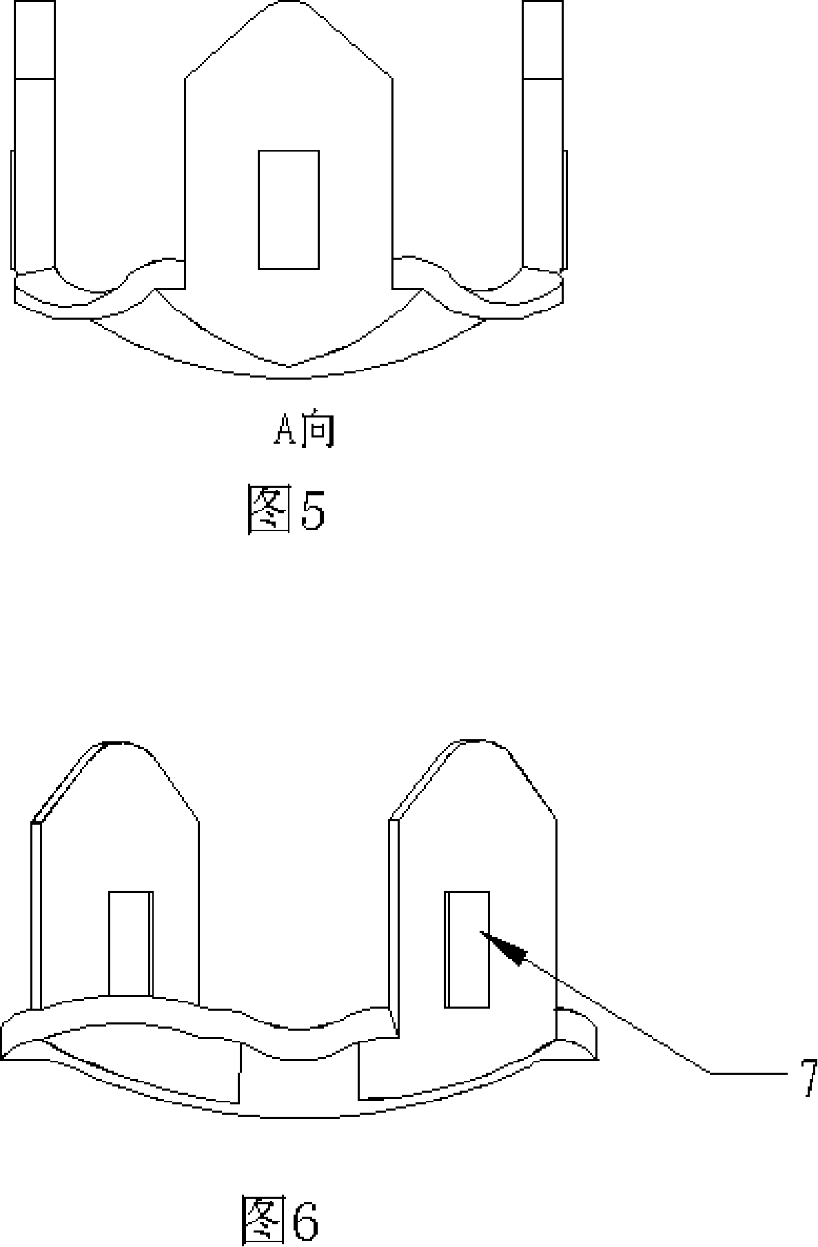
[0022] As shown in Figure 1, Figure 2, Figure 3, Figure 4 and Figure 5, the steel wire rope cross buckle of the present invention includes an upper card 1 and a lower card 2. Four jaws 3 are provided on the bottom surface of the lower card 2. The bottom surfaces of the card 1 and the lower card 2 are all concave arc-shaped bottom surfaces. Therefore, when the upper card 1 and the lower card 2 are in the buckled state, they have a convex and concave hollow cavity shape. After the cross buckle is fastened with more force, there is still enough space between the cards at the intersection of the steel wire ropes. The pressing force of the upper and lower cards on the steel wire rope is reduced, and the intersection of the steel wire rope can be well protected.

[0023] In this way, the steel wire rope cross buckle can be fastened by pressing and buckling the four claws 3 of the lower card 2 on the upper card 1 with only one pressing claw tool.

Example Embodiment

[0024] Embodiment two:

[0025] As shown in Fig. 6, Fig. 7, and Fig. 8, the bottom surfaces of the upper and lower cards are both concave arc-shaped, and both have two claws 3 and their positions can be interchanged.

[0026] At this time, the upper card 1 and the lower card 2 are interchangeable, and only a set of molds are needed for processing, but after the buckle installation, the pawl 3 needs to be pressed twice on the upper card 1 and the lower card 2.

[0027] As shown in the figure, the peripheral shape of the upper card 1 and the lower card 2 is circular. When the peripheral shape of the upper card 1 and the lower card 2 is a round or square regular shape, it is easy to process, the force is reasonable, and the claws are evenly arranged.

[0028] When the pawl 3 has a curved surface shape that is compatible with the upper card 1 and the lower card 2, it can better fit the upper card 1 and the lower card 2.

[0029] When there is a strip convex shape on the outer surface ...


PUM


Abstract

The invention discloses a steel wire rope cross-fixation device used for wire rope net, i.e. a cruciform latch which comprises an upper latching sheet (1), a lower latching sheet (2), and at least two claws (3) equipped at the bottom of the upper latching sheet (1) and/or the lower latching sheet (2). The bottom surfaces of the upper latching sheet (1) and the lower latching sheet (2) are shaped to a depressed arc surface. Crisscross grooves are correspondingly formed on the inner surfaces of the upper and the lower latching sheets. The circumferences of the upper and the lower latching sheets extend along the crisscross grooves out of the claws (3), forming a smooth notch (5) when the upper and the lower latching sheets are closed oppositely. The steel wire rope cross-fixation device solves the problem that the steel wire rope is easy to be damaged in the prior art, and has the advantages of good appearance, reduced material consumption, no need of perforation and low processing cost.

Description

technical field [0001] The invention relates to a fixed connection piece of a wire rope net, in particular to a wire rope cross fixing device applied to the wire rope net. Background technique [0002] In slope protection projects on both sides of roads and railways, steel wire rope nets are laid as protective nets. The intersection of wire ropes needs to be connected with a cross-shaped fixing device. As the utility model patent of CN2419417Y, the Chinese patent notification number discloses a cross buckle adopting upper and lower card structures, which is composed of square upper and lower cards. During use, because the upper and lower cards of this kind of steel wire rope cross buckle are planes, it is easy to cause damage to the steel wire rope when the buckle is tightened by mechanical force, which reduces the reliability of the steel wire rope net. Contents of the invention [0003] In order to overcome the disadvantage that the existing steel wire rope cross buckl...

Claims


Application Information

Patent Timeline
IPC IPC(8): E01F7/04F16G11/00
Inventor 杨涛
Owner 布鲁克(苏州)工程有限公司
Why Eureka
Try Eureka