Storing device for liquefied gas fuel

A storage device and liquefied gas technology, applied in the direction of liquid fuel feeder, oil supply device, power device, etc., can solve the problems of heavy weight, consumption of liquefied gas fuel, high purchase cost or manufacturing cost, etc.

Inactive Publication Date: 2008-01-16
CENTRAL MOTOR WHEEL CO LTD
View PDF1 Cites 3 Cited by
  • Summary
  • Abstract
  • Description
  • Claims
  • Application Information

AI Technical Summary

Problems solved by technology

Therefore, in practice, the storage amount of the liquefied gas fuel in each storage tank cannot be equalized, resulting in uneven consumption of the liquefied gas fuel, and there is a problem that the liquefied gas fuel pressure-fed to the engine tends to become unstable.
[0009] In addition, in the feed pump for pumping the liquefied gas fuel to the engine, a pump and a motor for pumping the liquefied gas fuel at a relatively high pressure are required, and an inverter for controlling the discharge amount is required. With these parts installed, the weight becomes heavy
Therefore, as described above, in a structure in which a plurality of storage tanks are loaded and a charge pump is arranged in each storage tank, the fuel consumption thereof deteriorates due to an increase in the weight of the vehicle as a whole
In addition, since the feed pump is a component with the above functions, its own purchase cost or manufacturing cost is relatively high, and the cost also increases accordingly.

Method used


Image

  • Storing device for liquefied gas fuel
  • Storing device for liquefied gas fuel
  • Storing device for liquefied gas fuel

Examples


Embodiment 1

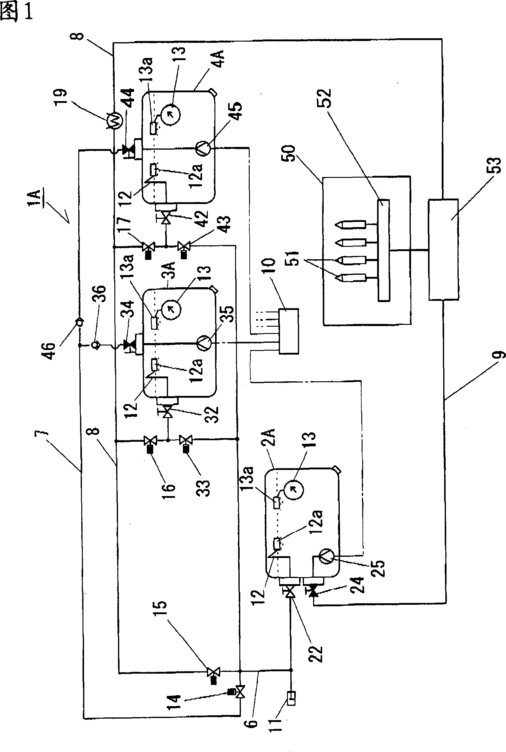
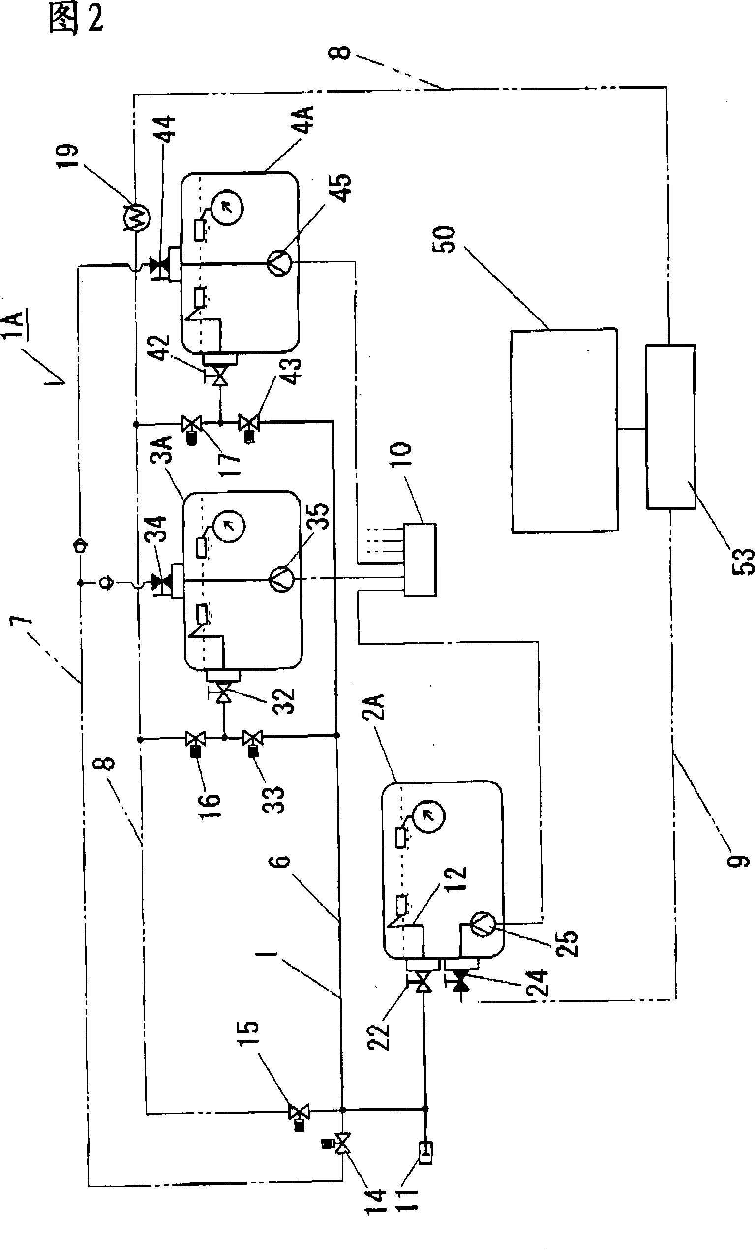
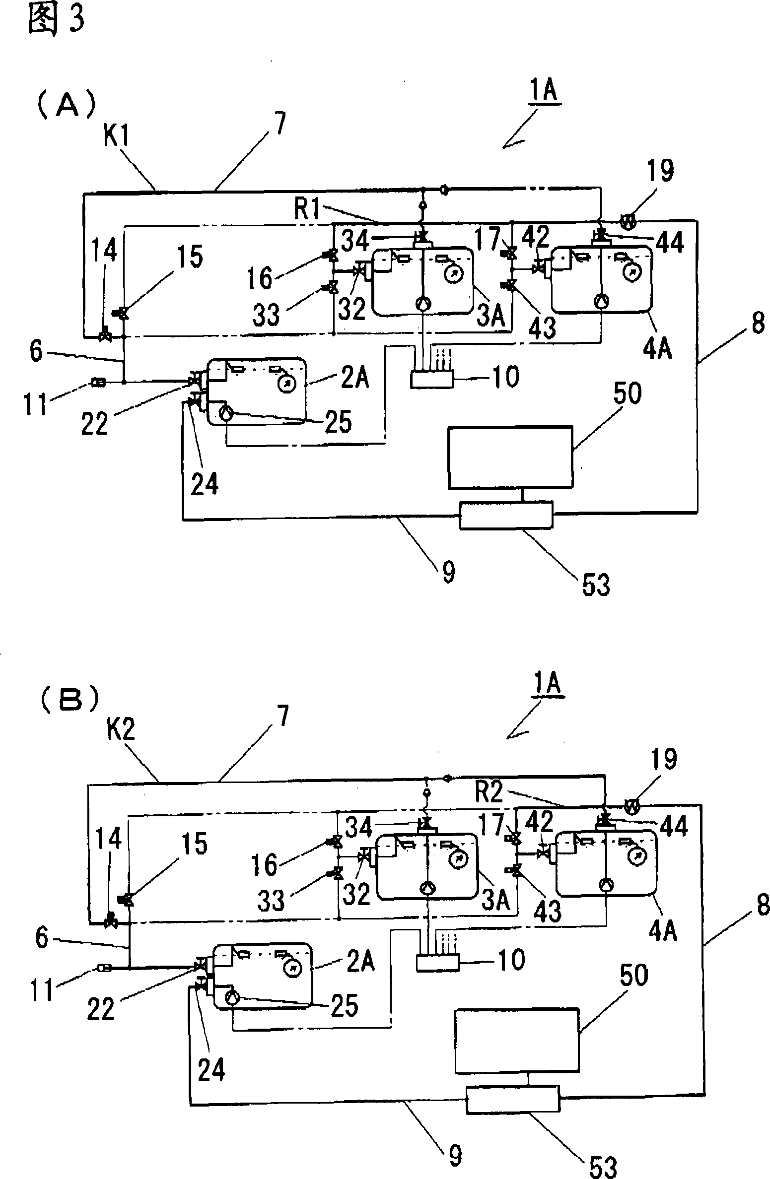
[0064] The liquefied gas fuel storage device 1A of this embodiment is mounted on an automobile and stores liquefied gas fuel as fuel for the engine 50 thereof. Fig. 1 is a conceptual diagram of a storage device 1A for liquefied gas fuel, which is equipped with a first storage tank 2A ​​and two second storage tanks 3A, 4A, a total of three storage tanks.

[0065] In the liquefied gas fuel storage device 1A, a quick joint 11 that can be detached from a filling gun (not shown) that injects liquefied gas fuel from the outside is installed. Filling pipe 6 of the second storage tank 3A, 4A. Here, the filling pipe 6 is branched to communicate with the filling valve 22 disposed on the first storage tank 2A, the filling valve 32 disposed on the second storage tank 3A, and the filling valve 42 disposed on the second storage tank 4A. connect. Furthermore, at positions immediately upstream of the filling valves 32 and 42 of the second storage tanks 3A and 4A in the filling pipe 6 , stop v...

Embodiment 2

[0090] In the liquefied gas fuel storage device 1B of the second embodiment, as shown in FIG. 4 , there are two second storage tanks 3B, 4B, and heaters 61 , 62 are provided at the lower positions inside each. Then, in the second storage tanks 3B, 4B, the suction pipes 63 , 64 communicating with the supply pipe 7 via the respective supply take-out valves 34 , 44 are respectively disposed therein. Here, the lower ends of the respective suction pipes 63 and 64 are provided at positions close to the bottom of the tank. That is, the positions of the lower ends of the suction pipes 63 and 64 become the lower limits of the second storage tanks 3B and 4B where the liquefied gas fuel can be supplied.

[0091] In addition, in the second embodiment, as in the first embodiment, a control processing device 10 for controlling the operation of each pump or valve is provided, and the above-mentioned heaters 61 and 62 are controlled by the control processing device 10 . The control processin...

Embodiment 3

[0097] In the liquefied gas fuel storage device 1C of the third embodiment, the second storage tanks 3C, 4C with the heaters 61, 62 removed from the structure of the above-mentioned embodiment 2 are installed, and at the same time, the cooling of the fuel is controlled by the control processing device 10. The device 19 operates to cool the high-temperature liquefied gas fuel returned by the engine 50 to a specified temperature range. In this configuration, as shown in FIG. 5 , the supply pumps 35 and 45 of the first embodiment and the heaters 61 and 62 of the second embodiment are not provided.

[0098] Here, as the operation control of the fuel cooler 19 performed by the control processing device 10, the remaining liquefied gas fuel flows to the second storage tanks 3C, 4C in a predetermined temperature range, so that the second storage tanks 3C, 4C The temperature of the liquefied gas fuel in 4C is higher than that in the first storage tank 2A. That is, as in the above-ment...


PUM


Abstract

A plan for the liquid gas fuel used storage device which can increase the storage amount of the liquid gas fuel, and it can steadily press and provide the liquid gas to the engine. The time the device presses and provides the liquid gas fuel used feed pump (25) in the first storage box (2A) to the engine (50) the device uses the fuel feeding device to feed the liquid gas fuel in the second storage box (3A, 4A) to the first storage box (2A) by means of the feeding line (K1, K2) along with the consumption of the liquid gas fuel in the first storage box (2A). As the composition can increase the storage amount of the liquid gas fuel the device can prolong the sustaining distance of the vehicle. Besides, the device can steadily and accurately convey the liquid gas fuel as the liquid gas fuel which is pressed and provide to the engine (50) is restricted to be only the fuel stored in the first storage box (2A).

Description

technical field [0001] The present invention relates to a storage device for liquefied gas fuel which stores liquefied gas fuel used as vehicle fuel and pressurizes the liquefied gas fuel to an engine. Background technique [0002] As exhaust regulations have been strengthened in recent years, vehicles using LPG (Liquefied Petroleum Gas) or DME (Dimethyl Ether) as fuel for the purpose of reducing pollution tend to increase. In particular, DME is valued because of its high cetane number and extremely low emission of PM and NOx. [0003] As a device using DME as fuel in this way, for example, as in Patent Document 1, a configuration has been proposed in which, among the DME fuel pressure-fed from the fuel tank to the engine, once the fuel remaining when the engine is stopped is sent to the purge tank Returned and depressurized, then sent to the fuel tank. This is because the DME fuel is pressure-fed from the fuel tank to the engine at high pressure, so it is depressurized in...

Claims


Application Information

Patent Timeline
Patent Type & Authority Applications(China)
IPC IPC(8): F02M21/00
CPCY02T10/32Y02T10/30B60K2015/03414B60K2015/03427F02M21/0215F02M21/0221F02M37/103
Inventor 岩月恵司稻垣秀幸
Owner CENTRAL MOTOR WHEEL CO LTD
Why Eureka
Try Eureka