Radar device

A technology of radar devices and optical circuits, applied in measuring devices, re-radiation of electromagnetic waves, utilization of re-radiation, etc., can solve the problem of reduced observation accuracy, difficulty in detecting low-brightness reflected light, and inability to correctly observe high-brightness reflected light, etc. problem to ensure responsiveness

Inactive Publication Date: 2008-01-16
ORMON CORP
View PDF1 Cites 16 Cited by
  • Summary
  • Abstract
  • Description
  • Claims
  • Application Information

AI Technical Summary

Problems solved by technology

[0007] In PIN photodiodes and avalanche photodiodes, there is a problem that the measured value of the incident light amount becomes saturated due to incident light of high brightness exceeding the detection limit. When the light-receiving sensitivity of the light-receiving circuit is increased by observing reflected light with low luminance, even if reflected light with low luminance can be observed, reflected light with high luminance cannot be accurately observed, and the observation accuracy decreases.
[0008] It is assumed that the problem of saturation of incident light can be solved by adding a diaphragm to the lens to suppress the amount of received light itself, but in this case, it is more difficult to detect low-brightness reflected light
In addition, if the bias voltage supplied to the avalanche photodiode is low, the light-receiving sensitivity of the avalanche photodiode itself is suppressed, and the problem of incident light saturation can be eliminated, but at this time, the parasitic capacitance of the avalanche photodiode itself increases rapidly and Responsiveness to high-speed signals deteriorates, and ranging performance also deteriorates

Method used


Image

  • Radar device
  • Radar device
  • Radar device

Examples


Embodiment Construction

[0037]Hereinafter, a radar device as an embodiment of the present invention will be described with reference to the drawings.

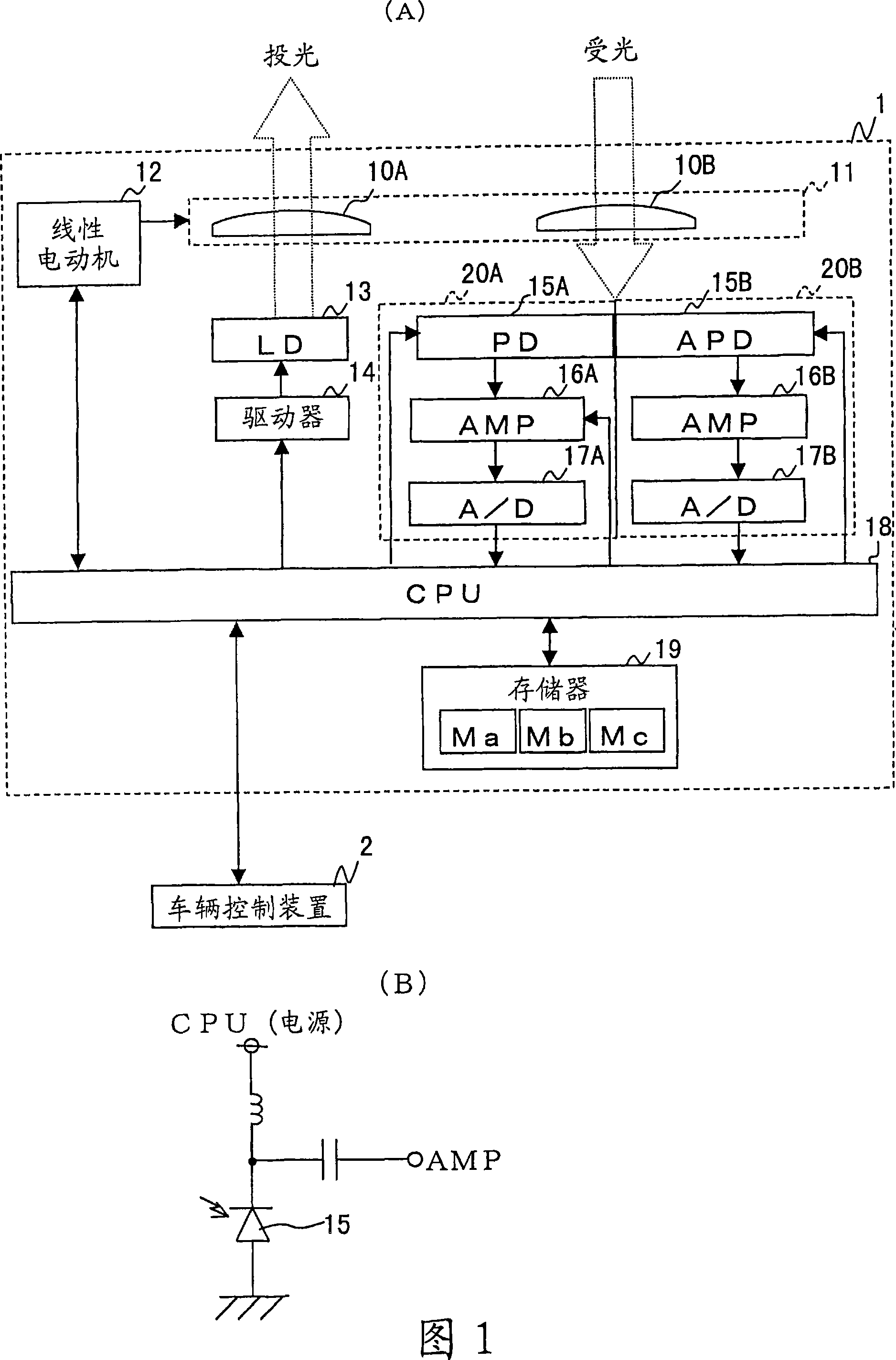
[0038] FIG. 1(A) is a block diagram showing the configuration of a radar device. The radar device 1 includes a lens unit 11 , a linear motor 12 , a laser diode (LD) 13 , a driver 14 , light receiving circuits 20A and 20B, a CPU 18 , and a memory 19 .

[0039] In the lens unit 11 , the light-projecting lens 10A and the light-receiving lens 10B are arranged on the same frame so that their respective optical axes are parallel. LD 13 is provided at the focal position of lens 10A, and PD 15A and APD 15B are provided at the focal position of lens 10B. The linear motor 12 is connected to the CPU 18, and the swing angle of the lens unit 11 is set according to the control of the CPU 18, so that the lens unit 11 (relative to the traveling direction of the vehicle) swings left and right.

[0040] LD 13 is connected to CPU 18 via driver 14 . The driver 14 sets...


PUM


Abstract

A radar device has a light projecting circuit for projecting light to an object. Reflected light from the object is received by a first light receiving circuit and a second light receiving circuit and converted into signals. The first and second light receiving circuits each have an activity range in which the outputted signal is proportional to the logarithm of the quantity of received light. The activity range of the first light receiving circuit is lower than the activity range of the second light receiving circuit.

Description

technical field [0001] The present invention relates to a radar device that irradiates near-infrared light or the like to a target object outdoors, receives the reflected light, and measures the distance to the target object. Background technique [0002] Conventionally, a radar device that scans the front with a laser beam such as near-infrared light is used outdoors to detect the presence or absence of a target object ahead from incident light including reflected light (for example, if it is a radar device for a car, the target object is a preceding vehicle. , obstacles, and pedestrians, etc.) and its distance measuring device has been practical. In a conventional radar device, a near-infrared laser beam irradiated from a laser diode is reflected from a target object, and the reflected light is received by a photodiode. ) time to measure the position of the target object. [0003] The S / N ratio of the PIN photodiode used in the radar device is low, so in order to improve...

Claims


Application Information

Patent Timeline
Patent Type & Authority Applications(China)
IPC IPC(8): G01S17/08G01S7/481
CPCG01S7/4802G01S17/42G01S7/4868
Inventor 石尾涉森川勇一藤冈良治
Owner ORMON CORP
Why Eureka
Try Eureka