Eureka AIR delivers breakthrough ideas for toughest innovation challenges, trusted by R&D personnel around the world.

Power amplification circuit and its initialization method and power amplification method

A technology of a power amplifier and an initialization method, applied in the directions of power amplifiers, improving amplifiers to improve efficiency, and improving amplifiers to reduce temperature/power supply voltage changes, etc. Excellent linearity, stable gain, and improved performance

Active Publication Date: 2010-05-26
AUCTUS TECH CO LTD
View PDF0 Cites 0 Cited by
  • Summary
  • Abstract
  • Description
  • Claims
  • Application Information

AI Technical Summary

Problems solved by technology

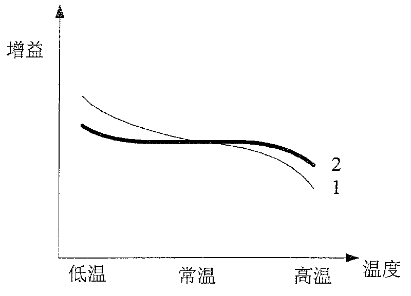
[0010] It can be seen that such temperature compensation cannot guarantee the high stability of the gain, and this temperature compensation for the gain cannot guarantee the linearity and efficiency of the power amplifier at high and low temperatures, and the requirements for linearity and efficiency are relatively high or have high The power amplifier with gain stability requirements cannot meet the requirements in this way

Method used


Image

  • Power amplification circuit and its initialization method and power amplification method
  • Power amplification circuit and its initialization method and power amplification method
  • Power amplification circuit and its initialization method and power amplification method

Examples


Embodiment Construction

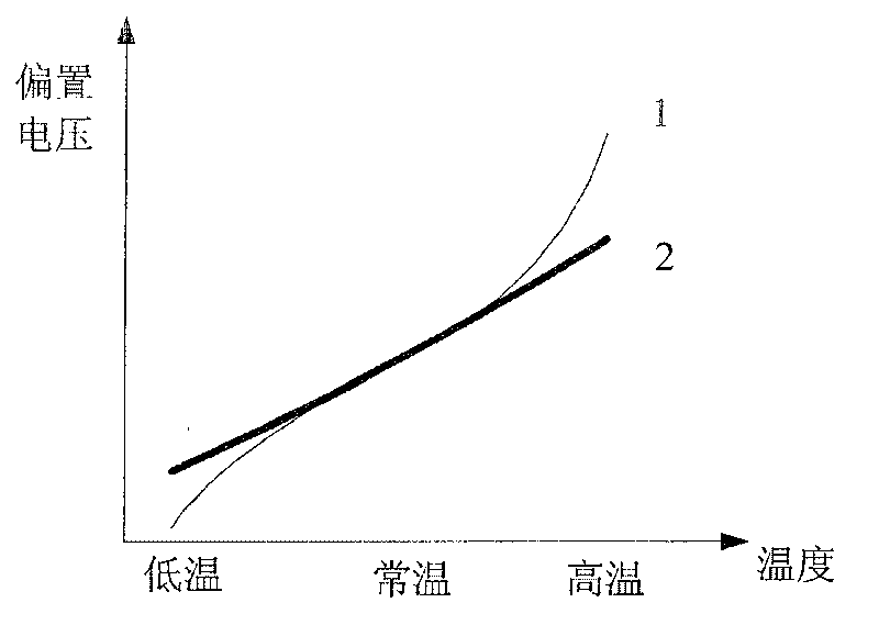
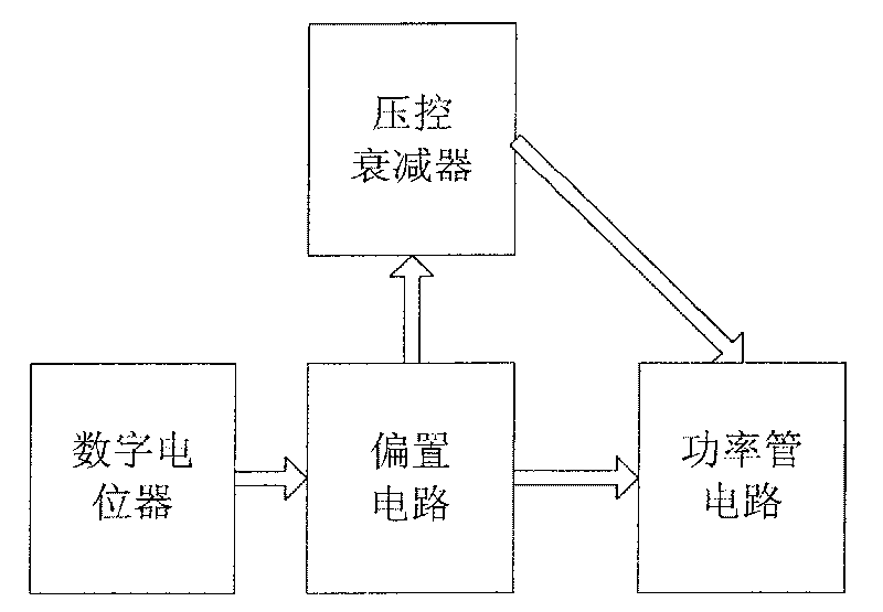
[0028] The structure of the power amplifier circuit of the present invention can be referred to image 3 and Figure 4 shown, including:

[0029] The power tube circuit amplifies the power of the input signal, in Figure 4 Among them, the power tube V1 and its peripheral circuits are responsible for amplifying the power, and then the amplified signal is output from the port RFout;

[0030] The voltage-controlled attenuator is connected to the power tube circuit to control and adjust the gain during power amplification. Figure 4 Among them, the voltage-controlled attenuator N1 is connected to the power tube V1 to control and adjust the gain of the entire power amplifier circuit;

[0031] The first bias circuit, connected to the bias end of the power tube circuit, controls the bias voltage of the power tube circuit; Figure 4 Among them, the first bias circuit is composed of the operational amplifier A1B and its surrounding circuits, and the bias circuit can adjust and cont...


PUM


Abstract

The invention discloses a power amplifier circuit comprising a digital potentiometer which comprises a temperature sensor, a memory, and a variable resistance, wherein the corresponding information oftemperature data and variable resistance value is kept in the memory; the variable resistance is connected with the bias circuit, controlling the linear, the efficiency, and the gain of the power amplifier circuit. The invention also discloses an initializing method for the power amplifier circuit, comprising variable resistance value in digital potentiometer when different temperature record makes the linear, the efficiency, and the gain of the circuit reach a good index. The invention also discloses a power amplifying method for power amplifier circuit, changing variable resistance value according to the temperature information collected by temperature sensor and regulating the power control circuit to keep good linear, efficiency, and gain under different temperature.

Description

technical field [0001] The invention relates to a circuit, especially a power amplifier circuit. The invention also relates to a power amplifier circuit initialization method and a power amplification method. Background technique [0002] The power amplifier is an essential part in a modern communication system, and its cost can account for about 30% in a base station. It is used to amplify the analog signal so that it can be transmitted easily. Its main parameters are gain, linearity and efficiency. [0003] Among them, the gain refers to the amplification factor of the power amplifier to the radio frequency signal, usually in dB, which is used to represent the ratio of the output signal of the power amplifier to the input signal. Usually the system will require the power amplifier to have a stable gain. [0004] Linearity characterizes whether the power amplifier can truly amplify the signal. The better the linearity of the power amplifier, the smaller the distortion ...

Claims


Application Information

Patent Timeline
Patent Type & Authority Patents(China)
IPC IPC(8): H03F1/02H03F1/32H03F1/30H03F3/20
Inventor 韩华袁安伟闫志国刘德复
Owner AUCTUS TECH CO LTD
Why Eureka
Eureka Blog
Learn More