Current constant and light adjusting control circuit for luminescent LED array

A light-adjusting control circuit and light-emitting diode technology, which is applied to lighting devices, lamp circuit layout, light sources, etc., can solve the problems of pulse interference, complex circuits, and high cost, and achieve the effect of low cost and simple circuit structure

Inactive Publication Date: 2008-01-16
SICHUAN UNIV
View PDF1 Cites 32 Cited by
  • Summary
  • Abstract
  • Description
  • Claims
  • Application Information

AI Technical Summary

Problems solved by technology

This kind of control circuit uses a duty cycle (PWM) to control the LED current,

Method used


Image

  • Current constant and light adjusting control circuit for luminescent LED array
  • Current constant and light adjusting control circuit for luminescent LED array
  • Current constant and light adjusting control circuit for luminescent LED array

Examples


Embodiment 1

[0025] In this embodiment, the lighting LED array 4 is composed of 30 lighting branches connected in parallel, and each lighting branch is made of 10 white LEDs in series.

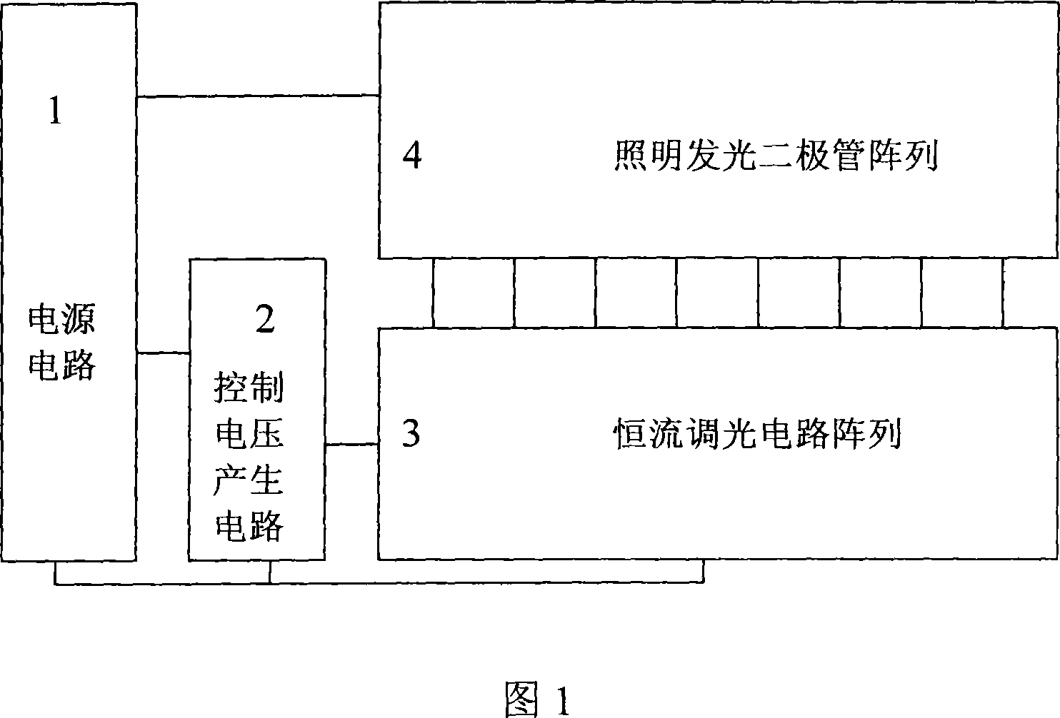
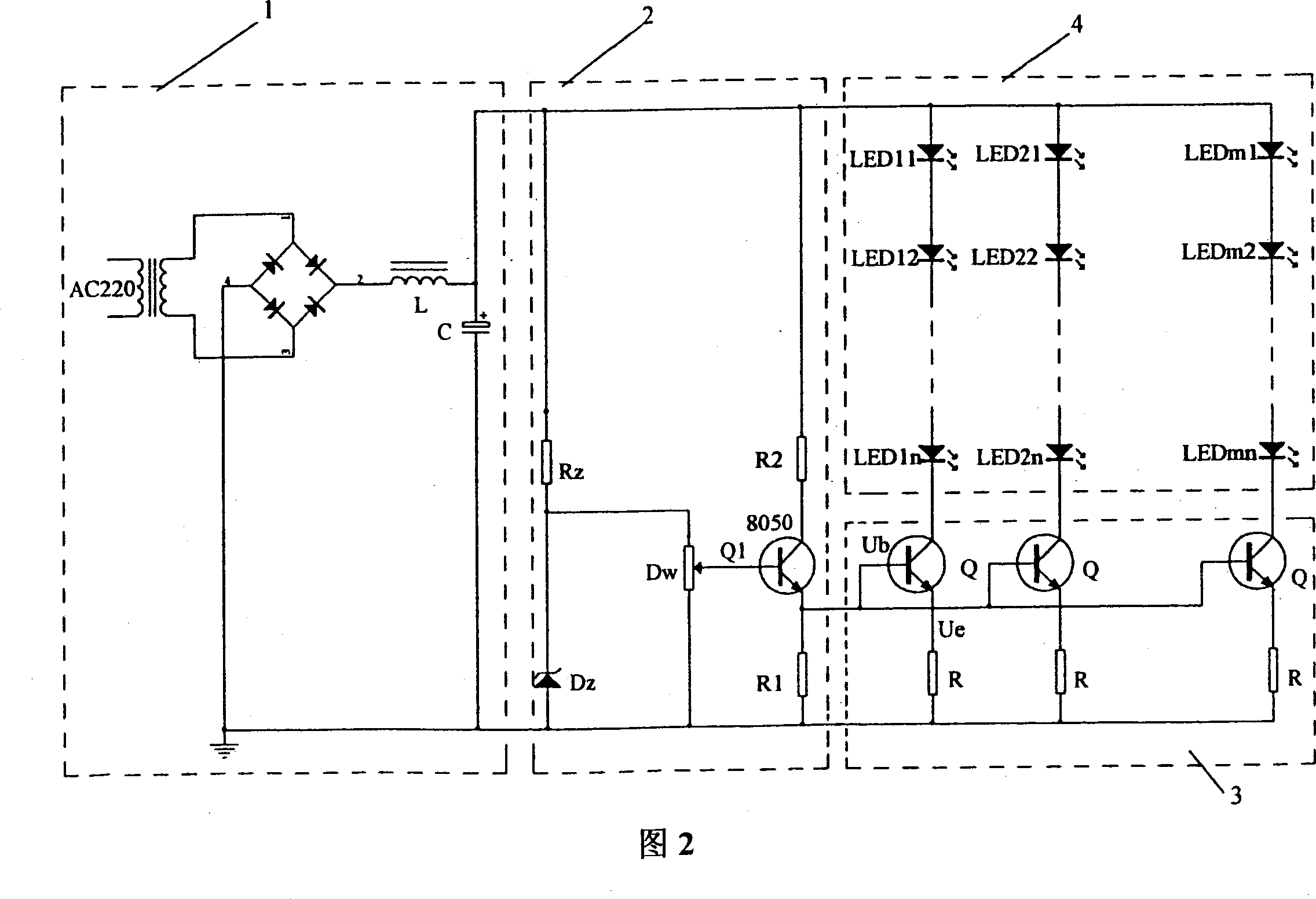
[0026] The constant current and dimming control circuit of the lighting LED array is shown in FIG. 2 , which includes a power supply circuit 1 , a control voltage generating circuit 2 and a constant current dimming circuit array 3 . The constant current dimming circuit array 3 contains 30 control branches, and each control branch is composed of an NPN transistor Q (selected as 8050) and a current feedback resistor R with a resistance value of 20 ohms (1% precision) connected in series. The control voltage generation circuit 2 includes a voltage stabilizing circuit composed of a current-limiting resistor Rz and a voltage stabilizing tube Dz (5-volt stabilizing tube), a potentiometer Dw connected in parallel with the voltage stabilizing tube Dz, and an NPN transistor Q1 (selecting 8050) and a resistor The em...

Embodiment 2

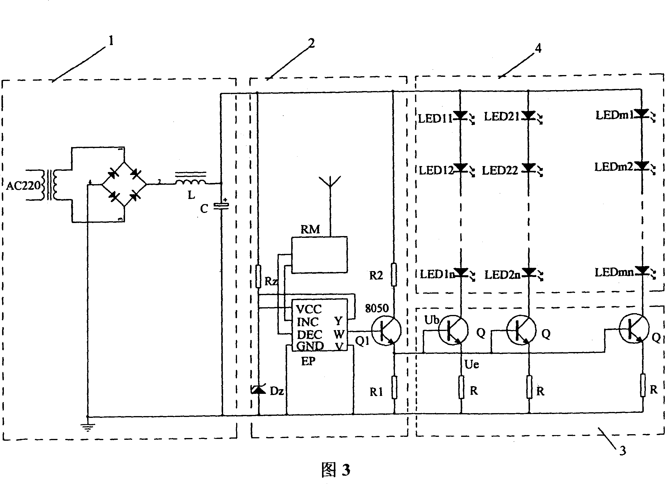
[0029] In this embodiment, the structure of the lighting LED array 4 and the number of white LEDs are the same as those in Embodiment 1. The constant current and dimming control circuit of the lighting LED array is shown in FIG. 2 , including a power supply circuit 1 , a control voltage generation circuit 2 and a constant current dimming circuit array 3 . The structures and electrical parameters of the power supply circuit 1 and the constant current dimming circuit array 3 are the same as those in the first embodiment. The difference from Embodiment 1 is the structure of the control voltage generating circuit 2 .

[0030] The control voltage generating circuit 2 in this embodiment includes a voltage stabilizing circuit composed of a current-limiting resistor Rz and a regulator tube Dz, an electronic potentiometer EP, a remote control receiver RM, and a remote control transmitter, which are composed of a triode Q1 and resistors R1 and R2. The emitter follower circuit; the inpu...


PUM


Abstract

A constant current and light regulating control circuit of light emitting diodes array for lighting is characterized in that the light emitting diodes array for lighting is formed by at least two lighting sub-circuits in parallel connection, each lighting sub-circuit is formed by at least two light emitting diodes in series connection. The constant current and light regulating control circuit includes a power supply circuit, a control voltage generation circuit, and a constant current light regulating circuit array. The constant current light regulating circuit array includes control sub-circuits at the same number as lighting sub-circuits in the light emitting diodes array for lighting, each control sub-circuit is formed by a triode and a current feedback resistor in series connection, collector of triode in each control sub-circuit is connected with cathode of the last diode in the correspondent lighting sub-circuit in the light emitting diodes array for lighting, and triode base electrodes in the control sub-circuits are connected in parallel to form a control point for the light emitting diodes array for lighting. Output terminal of the control voltage generation circuit is connected with control input terminal of the constant current light regulating circuits array to provide stable control voltage for the constant current light regulating circuits array.

Description

technical field [0001] The invention belongs to the constant current and dimming control circuit of light-emitting diodes (LED for short) for lighting, in particular to a constant current control circuit of a diode array composed of a plurality of LED lamp strings or branch circuits (usually 2 to 10 in a string) connected in parallel. flow and dimming control circuits. Background technique [0002] The LED illuminants used for area lighting are composed of dozens of light-emitting diodes, and as many as hundreds of thousands of light-emitting diodes. Usually, 2 to 10 LEDs are connected in series to form a lighting branch, and each lighting branch is connected in parallel to form an array structure. For lighting LED arrays, the basic requirement is uniform and stable brightness. For this reason, the LED current of each lighting branch needs to be kept constant and controllable. The existing technology generally adopts the method of overall voltage stabilization to control t...

Claims


Application Information

Patent Timeline
IPC IPC(8): H05B37/02
Inventor 吴仲光
Owner SICHUAN UNIV
Why Eureka
Try Eureka