Air conditioning system

An air-conditioning system and air-conditioning machine technology, applied in the direction of air-conditioning systems, air humidification systems, heating and ventilation control systems, etc., to achieve the effect of reducing the capacity of refrigerators and stabilizing temperature and humidity control

Active Publication Date: 2010-06-23
WETMASTER +1
View PDF3 Cites 0 Cited by
  • Summary
  • Abstract
  • Description
  • Claims
  • Application Information

AI Technical Summary

Problems solved by technology

[0007] However, in the invention described in Patent Document 1 or Patent Document 2, in order to make the distribution of the outside air supplied to the room uniform, a water humidifier must be installed in the corresponding place , therefore, there is a problem that the cost of piping construction for transporting air increases
In addition, when the water is dispersed in the room, it may cause an accident, and there is a problem that it is necessary to install a space and the uniformity of temperature and humidity is difficult.

Method used


Image

  • Air conditioning system
  • Air conditioning system
  • Air conditioning system

Examples


no. 2 Embodiment approach

[0081] (2-1) Structure

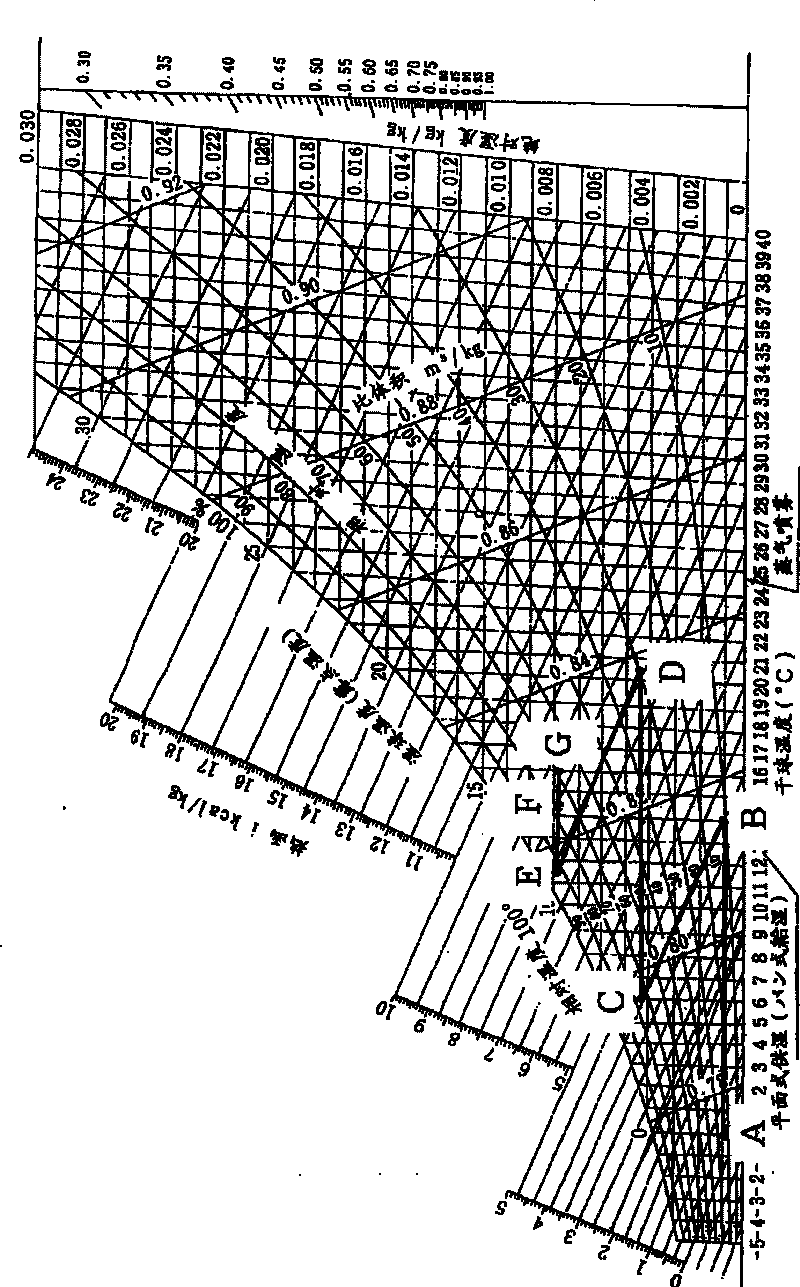
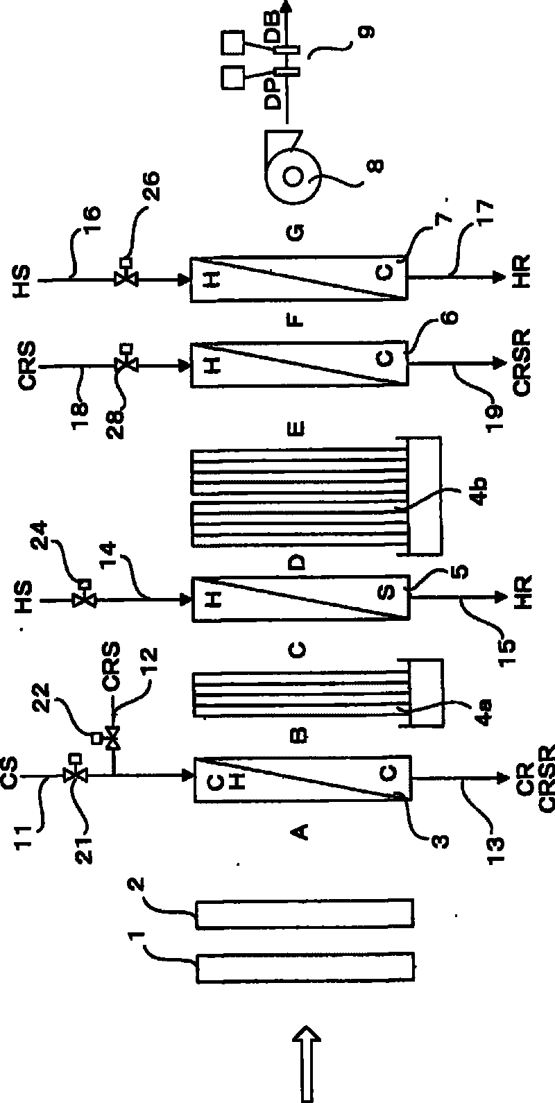
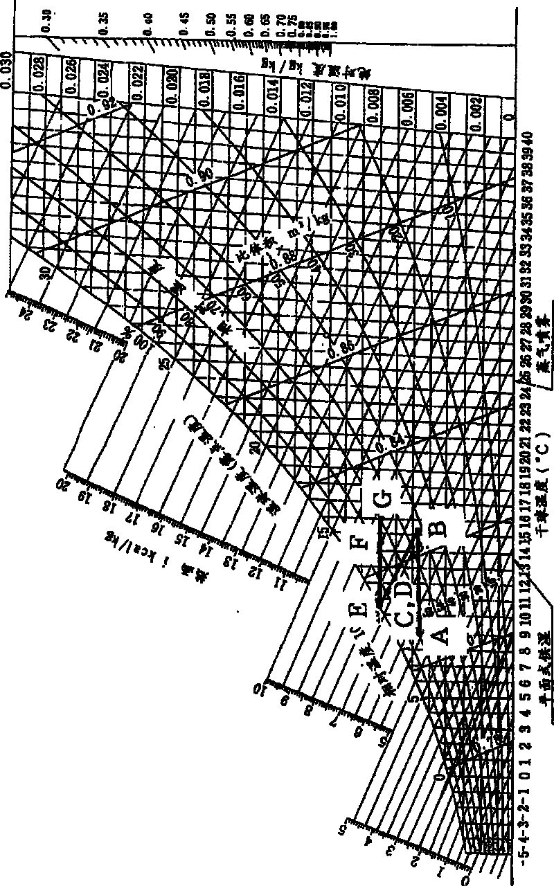
[0082] Image 6 It is a schematic diagram showing the structure of the air conditioning system of the present invention.

[0083] That is, inside the casing (not shown) of the air conditioner constituting the air conditioning system of the present embodiment, the prefilter 1 and the neutral performance filter 2 are arranged in order from the air inlet side, and are constituted as a multistage type. The first cooling and heating coil 3a and the second cooling and heating coil 3b, the first vaporizing humidifier 4a arranged on the upstream side of the first cooling and heating coil 3a, the first cooling and heating coil The second vaporizing humidifier 4b between 3a and the second cooling and heating coil 3b, the third vaporizing humidifier 4c installed on the downstream side of the second cooling and heating coil 3b, the heating coil 5, the second 4 gasification humidifier 4d, reheating coil 6, second reheating coil 7, blower 8 for discharging the tre...

no. 3 Embodiment approach

[0110] In this embodiment, a heating device is incorporated in the CRS system supplied to the cooling and heating coil and the reheating coil.

[0111] That is, in this embodiment, if Figure 15 As shown, on the return cold water supply pipe 12 that supplies the return cold water to the second cooling and heating coil 3b, and on the reheat coil side return cold water supply pipe 18 that supplies the return cold water to the reheat coil 6, respectively A heating mechanism 30 is provided.

[0112] The air conditioning system of this embodiment with the above-mentioned structure is effective when the temperature of the returned cold water is low or the amount of returned cold water is small, and the amount of humidification is insufficient even if the cooling and heating coils are provided in multiple stages.

[0113] (4) Other implementations


PUM


Abstract

An air conditioning system that can perform stable temperature / humidity control and in which the capacity of a freezing machine and energy consumption can be reduced. A cold water supply line (11) and a return cold-water supply line (12) are connected to a cooling-cum-heating coil (3). A warm water supply line (14) is connected to a heating coil (5). The amount of water supplied from the cold water supply line (11) or the return cold-water supply line (12) to the cooling-cum-heating coil (3) is controlled so that the humidity of air to be treated is a desired set humidity. When the amount of humidification is insufficient, the amount of warm water supplied from the warm water supply line (14) to the heating coil (5) is controlled. Further, the amount of water supplied from the cold water supply line (11) to the cooling-cum-heating coil (3) and the amount of return cold-water supplied from a return cold-water supply line (18) to a reheating coil (6) are controlled so that the temperature of the air to be treated is a desired set temperature. When the amount of reheating heat is insufficient, the amount of warm water supplied from the warm water supply line (16) to a second reheating coil (7) is controlled.

Description

technical field [0001] The present invention relates to an air-conditioning system for adjusting the temperature and humidity of air to be processed, and more particularly to an improved air-conditioning system capable of achieving stable temperature and humidity control, reduction in refrigerator capacity, and energy saving. Background technique [0002] In electronic industry factories, precision machinery industry factories, food storage warehouses, experimental animal breeding rooms, biological clean rooms, etc., since it is necessary to maintain a constant indoor environment such as temperature and humidity, it is necessary to use timely temperature control. Humidity-regulated air conditioning system. [0003] As such an air conditioning system, there is a system disclosed in Patent Document 1 or Patent Document 2, for example. That is, the invention described in Patent Document 1 or Patent Document 2 utilizes the cooling capacity of the outside air in winter, so the ...

Claims


Application Information

Patent Timeline
Patent Type & Authority Patents(China)
IPC IPC(8): F24F3/14F24F6/00F24F6/08F24F11/02
CPCF24F3/14F24F3/153F24F6/08F24F2110/20
Inventor 海老根猛
Owner WETMASTER
Why Eureka
Try Eureka