Floater type liquid container

A liquid accumulator and float type technology, which is applied in the field of liquid accumulators in the field of refrigeration and air conditioning, can solve the problems of inconvenient production, installation and management of liquid accumulators, high cost, and increase the design cost of air conditioners, etc. Unify road design and reduce the effect of design

Active Publication Date: 2011-07-20
SHANGHAI HITACHI ELECTRICAL APPLIANCES CO LTD
View PDF0 Cites 0 Cited by
  • Summary
  • Abstract
  • Description
  • Claims
  • Application Information

AI Technical Summary

Problems solved by technology

[0004] In order to ensure that the liquid refrigerant does not enter the cylinder, the volume of the accumulator required by the compressor with a larger amount of refrigerant sealed is also larger, resulting in different types of compressors corresponding to different volumes of the accumulator, and even in some cases due to More refrigerant is required, and the system needs to add an auxiliary accumulator, which causes a lot of inconvenience in the production, installation and management of the accumulator, and the cost is very high
In addition, the large number of liquid receivers also leads to the corresponding piping design of the air conditioner. The design of the air conditioning piping needs to be diversified, which will definitely increase the cost of air conditioning design and manufacturing.

Method used


Image

  • Floater type liquid container
  • Floater type liquid container
  • Floater type liquid container

Examples


Embodiment Construction

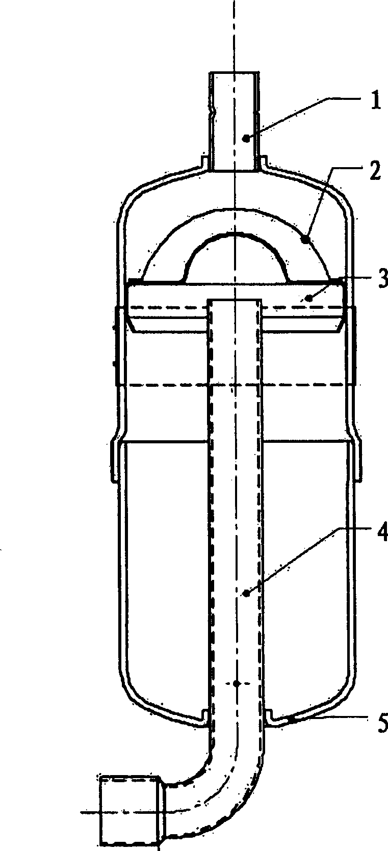
[0013] At present, in most small and medium-sized domestic refrigeration systems, the liquid receiver used by the compressor is a copper or iron cylindrical container with a structure such as figure 1 As shown, it includes a reservoir inlet pipe 1, a filter screen 2, a bracket 3, an exhaust pipe 4, and a housing 5. Wherein, the intake pipe 1 is connected to the upper part of the housing 5 and opens into the housing 5 . The exhaust pipe 4 extends into the casing 5 from the lower part of the outer casing 5 and opens into the casing 5 . The intake pipe 1 and the exhaust pipe 4 are aligned centrally and spaced longitudinally. The filter screen is arranged between the opening of the intake pipe 1 and the opening of the exhaust pipe 4 to prevent metal impurities in the system from entering the compressor and causing the compressor to stall.

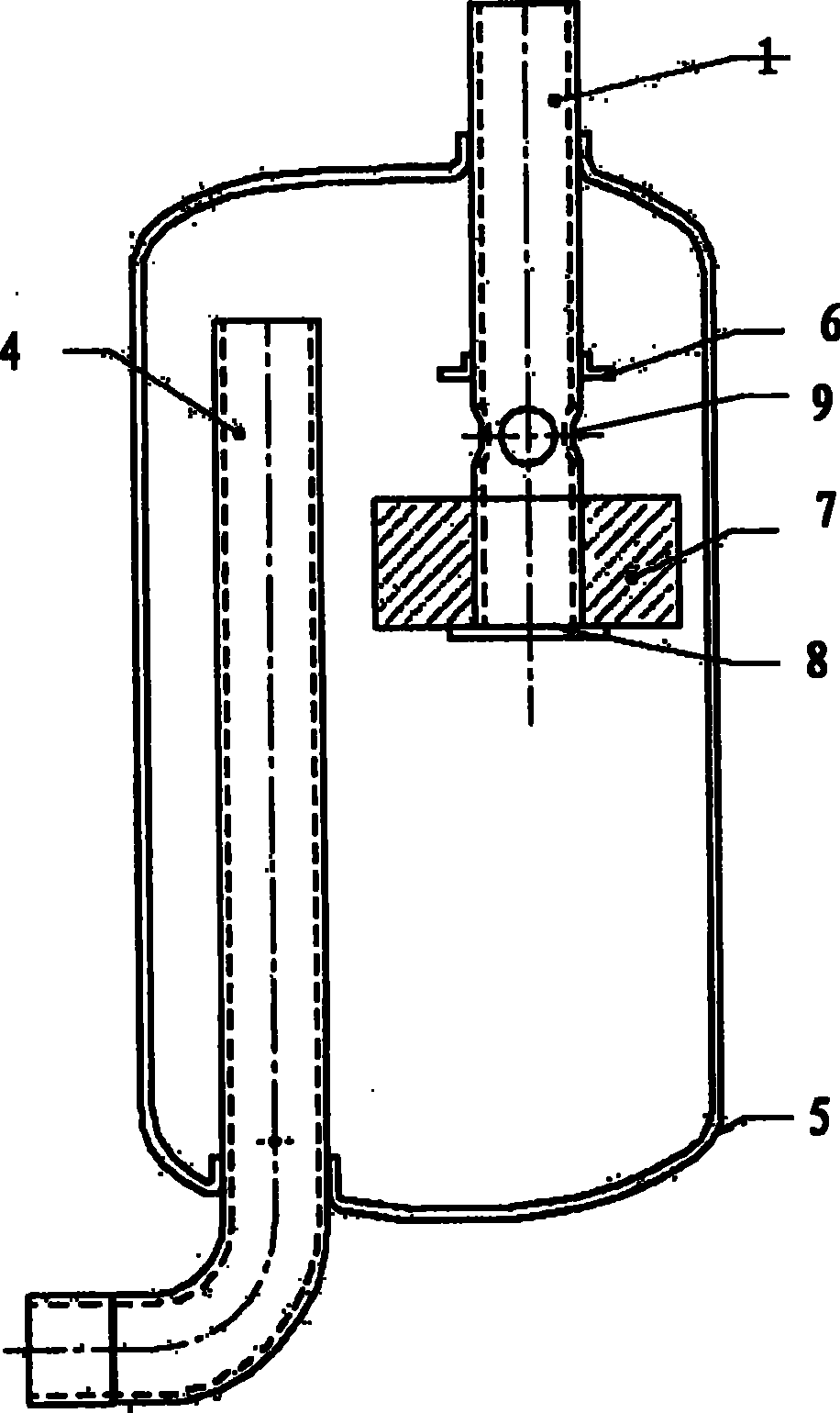
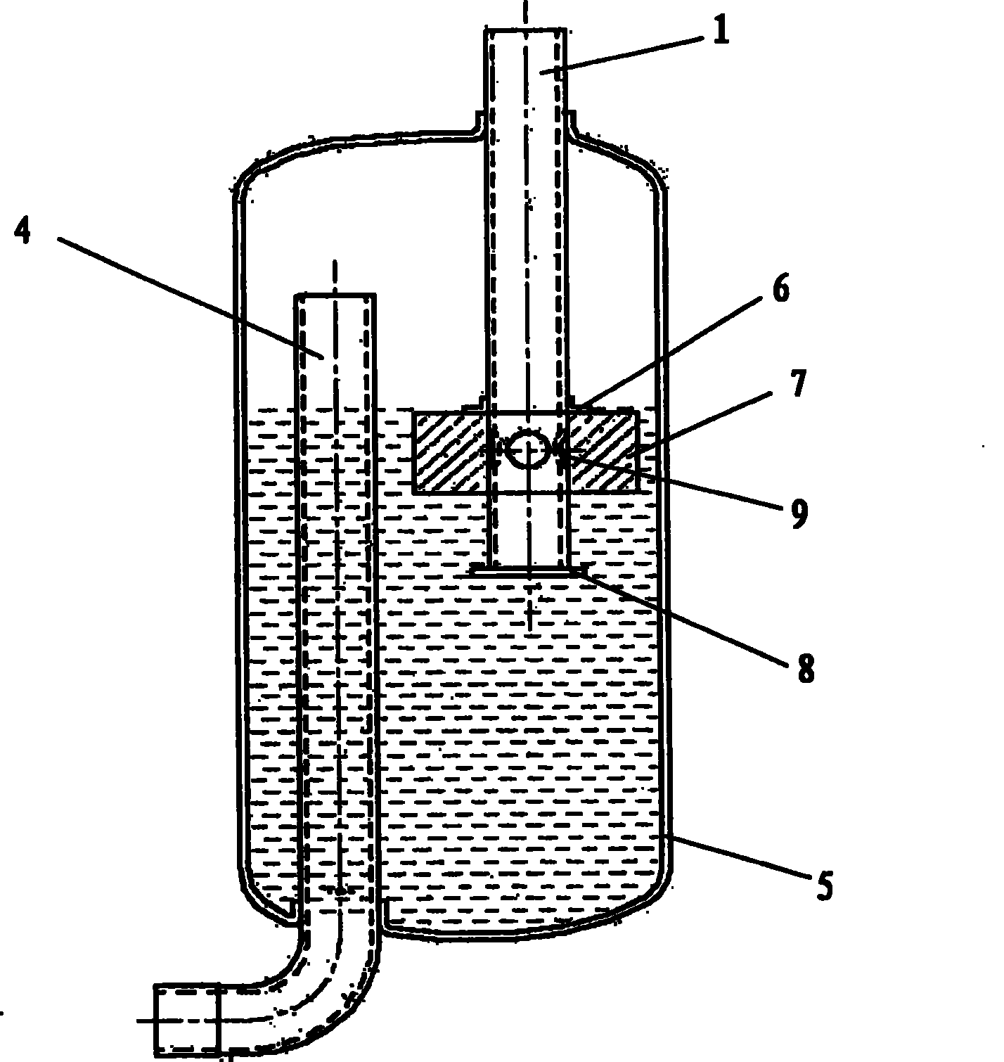
[0014] figure 2 It is a schematic diagram of the structure of the embodiment of the float type accumulator of the present invention in nor...


PUM


Abstract

The invention relates to a float type reservoir, which comprises an air-intake pipe (1), an air exhaust pipe (4) and a casing (5). The air-intake pipe (1) extends in from the upper part of the casing (5); the air exhaust pipe (4) extends in from the lower part of the casing (5). The invention is characterized in that, the float type reservoir additionally comprises a float (7) in the casing (5), an upper limit ring (6) and a lower limit ring (8). The lower end of the air-intake pipe (1) is closed in the casing, and the side of the part of the air-intake pipe (1) in the casing is provided withat least one through hole (9) for air admission; the upper limit ring (6) and the lower limit ring (8) are respectively located at the upper and the lower side of the through hole (9), and are fixed on the air-intake pipe (1); the float (7) is movably looped on the air-intake pipe (1) between the upper limit ring (6) and the lower limit ring (8); the height of the float (7) is less than the distance between the lower edge of the through hole (9) and the lower limit ring (8), but bigger than the distance between the lower edge of the through hole (9) and the upper limit ring (6); the air exhaust pipe (4) and the float (7) are separated in cross direction. The reservoir prevents liquid impact in a compressor through enclosing the air inlet by the buoyancy of the liquid refrigerant.

Description

technical field [0001] The invention relates to a liquid accumulator, in particular to a liquid accumulator used in the field of refrigeration and air conditioning. Background technique [0002] In the field of refrigeration and air conditioning, the accumulator is an auxiliary component of the compressor. It is usually connected with the compressor. connected. [0003] The function of the liquid receiver is to store liquid refrigerant, which can effectively prevent the liquid refrigerant from flowing into the compressor when the compressor is running in an unstable state, causing liquid shock and damaging the compressor components. The effective volume of the accumulator is the volume below the top of the exhaust pipe. The design of the effective volume is determined according to the amount of air-conditioning refrigerant enclosed. Air conditioners of different specifications correspond to different amounts of refrigerant enclosed. In order to prevent liquid refrigerant fr...

Claims


Application Information

Patent Timeline
Patent Type & Authority Patents(China)
IPC IPC(8): F25B43/00
Inventor 王艳珍周易刘春慧
Owner SHANGHAI HITACHI ELECTRICAL APPLIANCES CO LTD
Why Eureka
Try Eureka