
System and method for in-context volume visualization using virtual incision

一种体积、切割区域的技术,应用在体绘制领域,能够解决不能应用重要性驱动等问题

Inactive Publication Date: 2008-01-23
SIEMENS MEDICAL SOLUTIONS USA INC
View PDF0 Cites 14 Cited by
  • Summary
  • Abstract
  • Description
  • Claims
  • Application Information

AI Technical Summary

Problems solved by technology

Therefore, importance-driven visualization cannot be applied in this case

Method used


Image

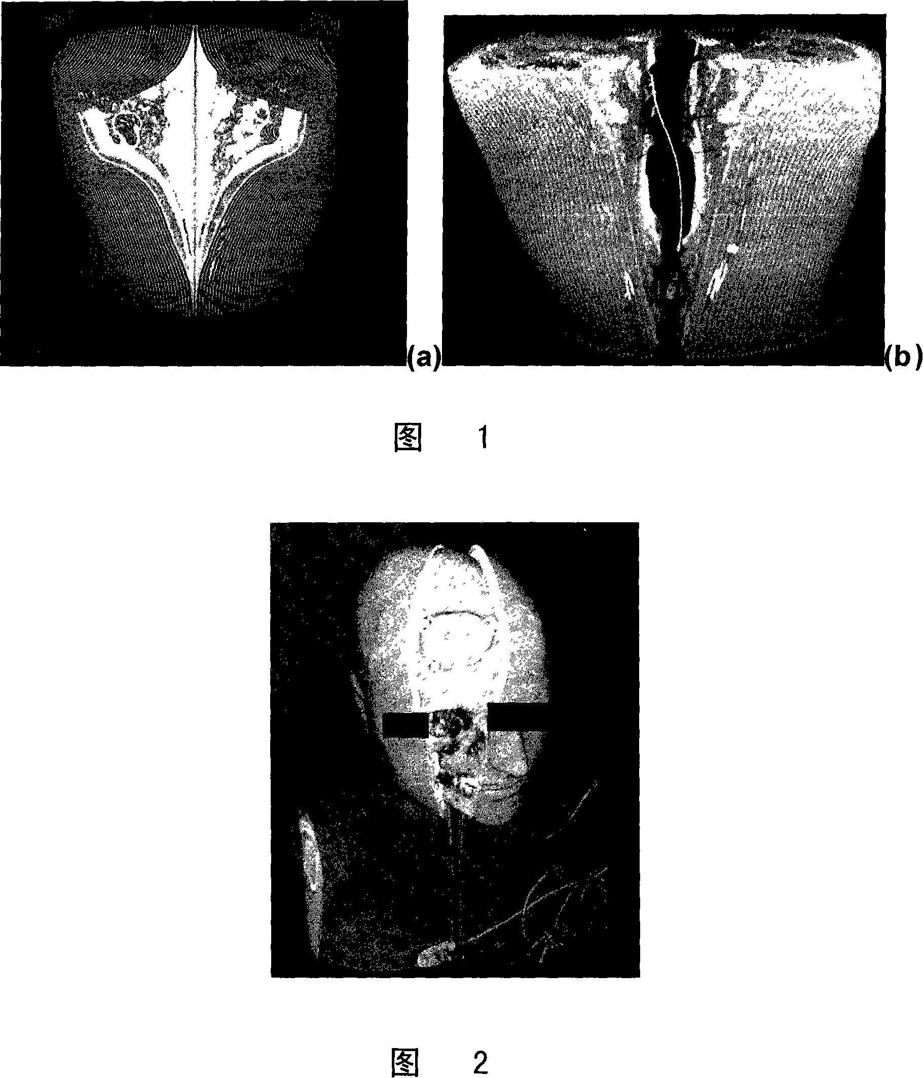
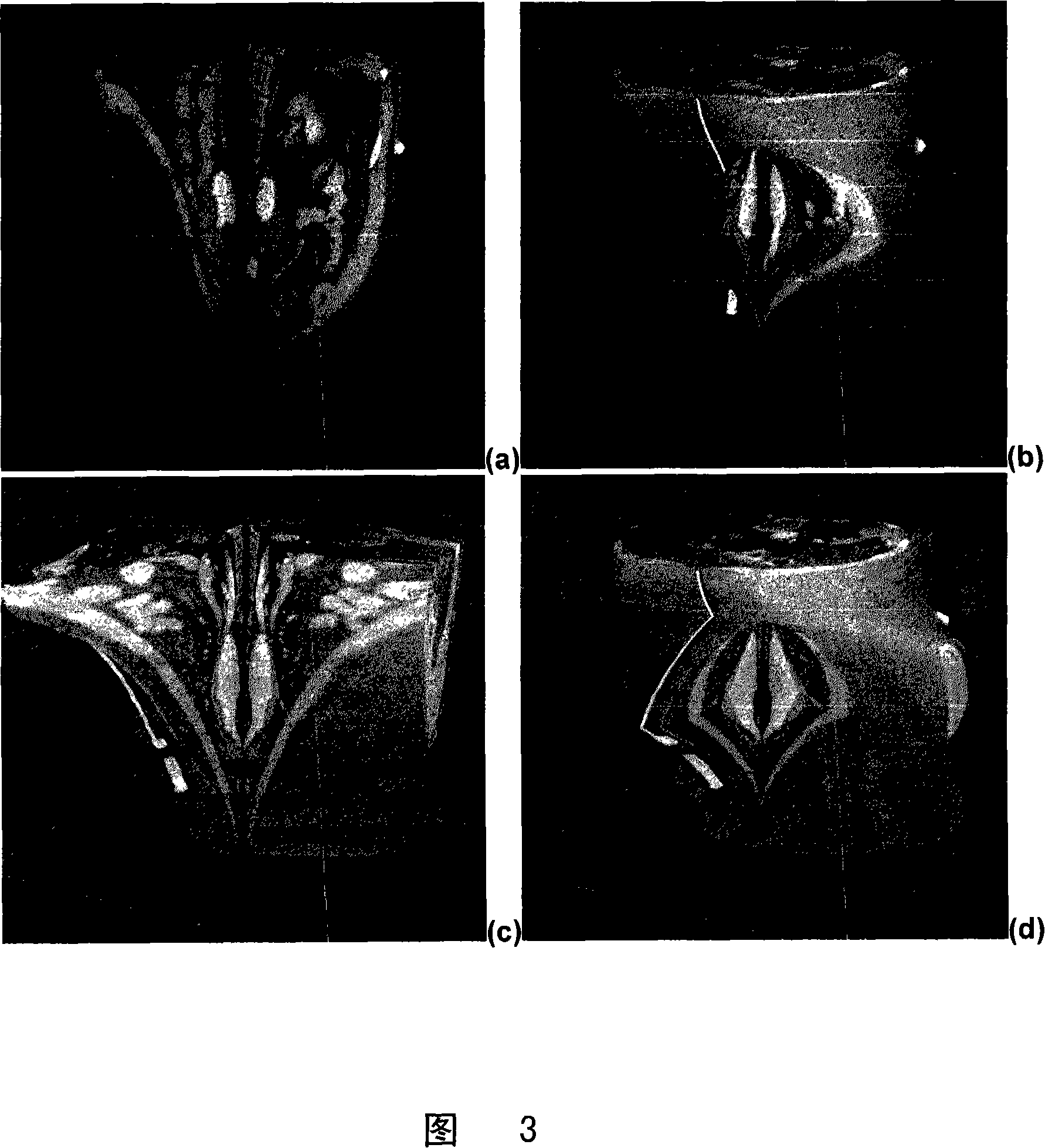
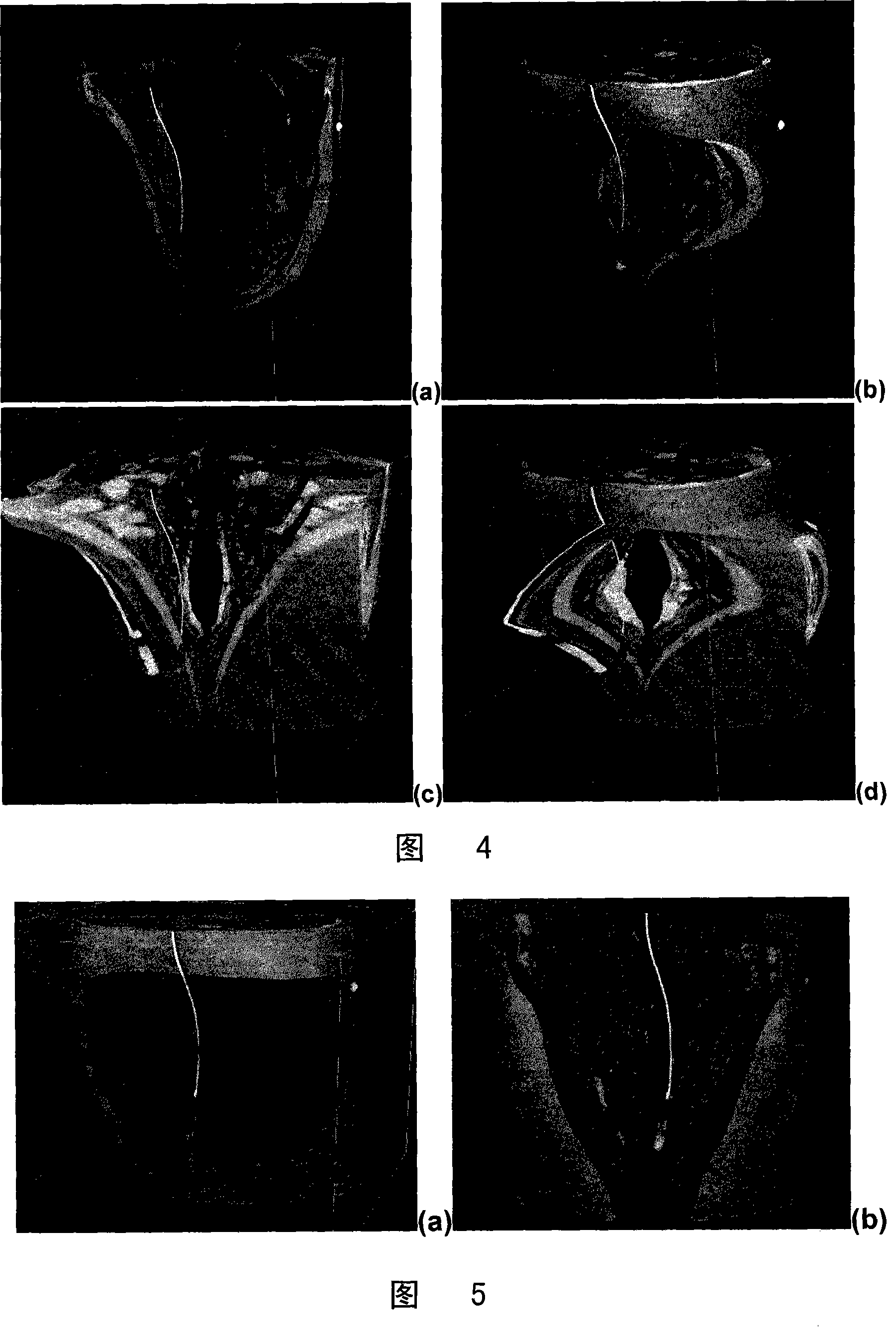
  • System and method for in-context volume visualization using virtual incision
  • System and method for in-context volume visualization using virtual incision
  • System and method for in-context volume visualization using virtual incision

Examples


Embodiment Construction

[0034] Exemplary embodiments of the invention described herein generally include systems and methods for in-context volume visualization. Therefore, while the invention is susceptible to various modifications and alternative forms, specific embodiments thereof are shown by way of example in the drawings and will be described in detail herein. It should be understood, however, that there is no intention to limit the invention to the particular forms disclosed, but on the contrary, the intention is to cover all modifications, equivalents, and alternatives falling within the spirit and scope of the invention.

[0035] As used herein, the term "image" refers to multidimensional data composed of discrete image elements (ie, pixels for 2-D images and voxels for 3-D images). The image may be, for example, a medical image of the subject collected by computed tomography, magnetic resonance imaging, ultrasound, or any other medical imaging system known to those skilled in the art. Imag...


PUM


Abstract

A method for volume rendering a digitized medical image includes providing a digitized medical image volume comprising a plurality of intensities on a 3-dimensional grid of points, providing a projection plane comprising a 2-dimensional lattice of points onto which rendering rays are projected from a viewing point through the image volume, advancing a sampling point along a ray through the image volume, generating an incision region within the image volume, determining whether the sampling point is within the incision region, where a first transfer function is applied to a sample value interpolated from a first volume if the sampling point is within the incision region, and a second transfer function is applied to a sample value interpolated from a second volume if the sampling point is outside the incision region, and accumulating the output of the transfer function.

Description

[0001] Cross References to Related U.S. Applications [0002] This application claims priority to U.S. Provisional Application No. 60 / 775,193, "AN EFFICIENT DISPLAY TECHNIQUE FOR VIRTUALINCISION USING PROCEDURAL OPENING AND DEFORMATION FOR IN-CONTEXT VOLUME VISUALIZATION," filed February 21, 2006 by Engel et al., the contents of which are hereby Cited as reference. technical field [0003] The present disclosure relates to volume rendering, and more particularly to in-context volume visualization inside volumetric images. Background technique [0004] The basic principle of direct volume rendering is to sample volume datasets along rays in arbitrary directions and blend these samples together in the framebuffer. The densities read in the volume are converted to colors (RGBA) using a transfer function, usually encoded as a look-up table, before being blended. For this reason, blending is often referred to as alpha blending. When a sufficient number of samples are included,...

Claims


Application Information

Patent Timeline
Patent Type & Authority Applications(China)
IPC IPC(8): G06T15/00A61B6/03G06T15/08
CPCG06T19/00G06T15/08
Inventor K·恩格尔J·威廉斯
Owner SIEMENS MEDICAL SOLUTIONS USA INC
Learn More