Control system having a plurality of spatially distributed stations, and method for transmitting data in such a control system

A control system and space distribution technology, applied in the field of data transmission, can solve the problems of difficult transmission, difficult data transmission, Ethernet components, and the method of Ethernet components is not optimal, etc., to achieve the effect of flexible communication and flexible automation

Active Publication Date: 2008-01-23
PILZ (COMPANY)
View PDF1 Cites 17 Cited by
  • Summary
  • Abstract
  • Description
  • Claims
  • Application Information

AI Technical Summary

Problems solved by technology

[0013] However, the previously proposed method of using Ethernet components in automatic control systems is not optimal
Difficulties arise especially due to the transmission of safety-relevant control data, such as the transmission of emergency discon

Method used


Image

  • Control system having a plurality of spatially distributed stations, and method for transmitting data in such a control system
  • Control system having a plurality of spatially distributed stations, and method for transmitting data in such a control system
  • Control system having a plurality of spatially distributed stations, and method for transmitting data in such a control system

Examples


Embodiment Construction

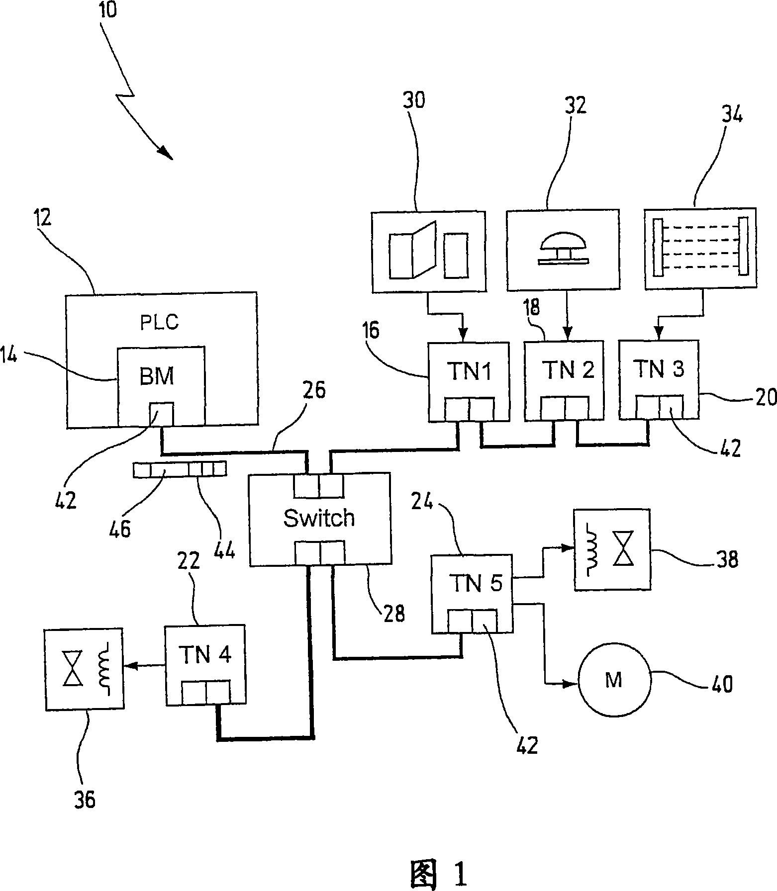
[0062] An exemplary embodiment of the novel control system is generally designated 10 in FIG. 1 .

[0063] The control system 10 includes a control unit 12 in the form of, for example, a programmable logic controller referred to herein as a PLC. Optionally, it can also be a different control unit, such as an Industrial PC. At the application level, the control unit 12 takes over the control of technical installations (not shown in detail here), for example production or delivery installations. In this regard, it processes process or status data from the device captured with sensors and generates control data that is used to operate the brakes. To communicate with the sensors and actuators, the control unit 12 uses a communication network implementing an exemplary embodiment of the novel method in the manner described below.

[0064] For communication with local sensors and actuators, the control unit 12 in this case has a so-called bus manager 14 , which is the first station...


PUM


Abstract

The method involves producing a data frame (46) with data fields by a station (14), and assigning one data field to another station. The data frame is transmitted from one station to next as a forwarding data frame (46', 46''). Last station (20) transmits the data frame as a returning data frame (46''') to the stations. The stations read external transmission data from the data fields of the returning data frame. Independent claims are also included for the following: (A) a control system for automatically controlling a device for transmitting data (B) a communication module for a station in a control system.

Description

technical field [0001] The invention relates to a method for transferring data in a control system having a plurality of spatially distributed stations interconnected via a communication medium, said stations being logically arranged into a group defining a first station, at least one In the second and last station, the method comprises the steps of: [0002] - said first station generates a data frame with a plurality of data fields, wherein each second and last station is explicitly allocated at least one data field for filling transmission data; [0003] - said first station sends said data frame as an output data frame to a second station in said group following said first station; [0004] - each second station receives said output data frame from its respective preceding station in said group, fills its assigned data field with transmission data, and sends an output data frame with said transmission data to said group the next stop in ; and [0005] - the last station...

Claims


Application Information

Patent Timeline
IPC IPC(8): G05B19/042
CPCH04L12/417
Inventor H·施文克尔K·乌哈斯R·斯派尔M·霍扎普费尔R·鲁普
Owner PILZ (COMPANY)
Why Eureka
Try Eureka