Inhaler
A technology for inhalation devices and inhalation ports, which is applied in the direction of inhalers, respirators, nebulizers for treatment, etc., can solve the problems of undesired sanitation and low therapeutic efficacy, and achieve the goal of ensuring reproducibility and reducing the amount of inhaled drugs Effect
- Summary
- Abstract
- Description
- Claims
- Application Information
AI Technical Summary
Problems solved by technology
Method used
Image
Examples
Embodiment approach 1
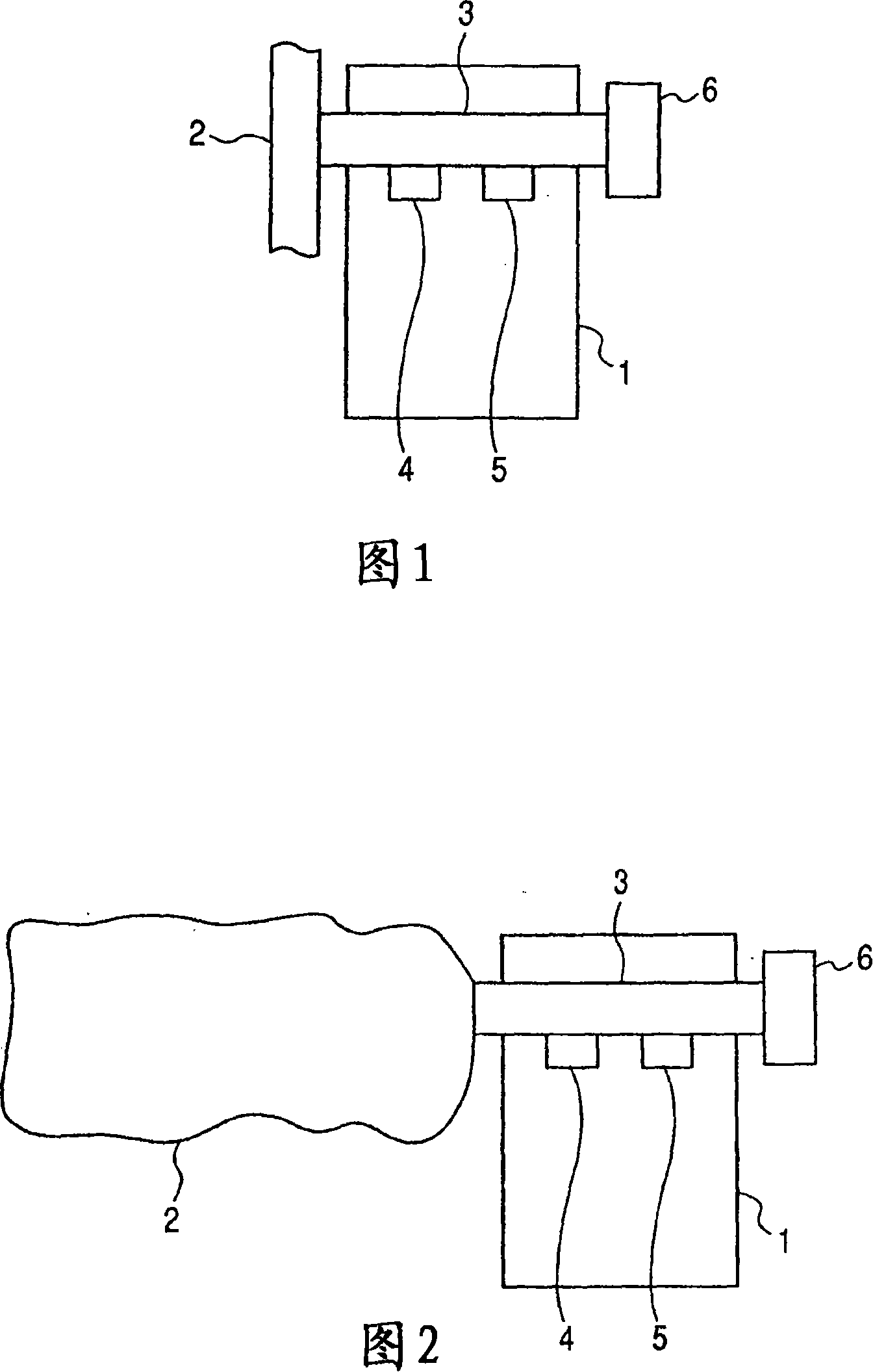
[0036] Fig. 1 partially illustrates an inhalation device as a first embodiment of the present invention. The inhalation device of the first embodiment of the present invention is characterized in that a container 2 serving as a gas storage means is provided at the portion which is conventionally open, in which container 2 is stored user's exhaled breath or other gas. The container 2 is connected to the flow path member 3 in the folded state, and the container 2 is designed so that the patient can send his or her exhaled air from the inhalation port 6 to the container 2 through the flow path. Furthermore, the inhalation device is constructed so as to provide the pressure sensor 5 in the air flow path so as to detect negative pressure generated in the air flow path by patient inhalation, and to atomize the medicine from the spray head 4 to the inside of the nozzle synchronously with the detection. The flow path member 3 is preferably detachably connected to the device main body ...
Embodiment approach 2
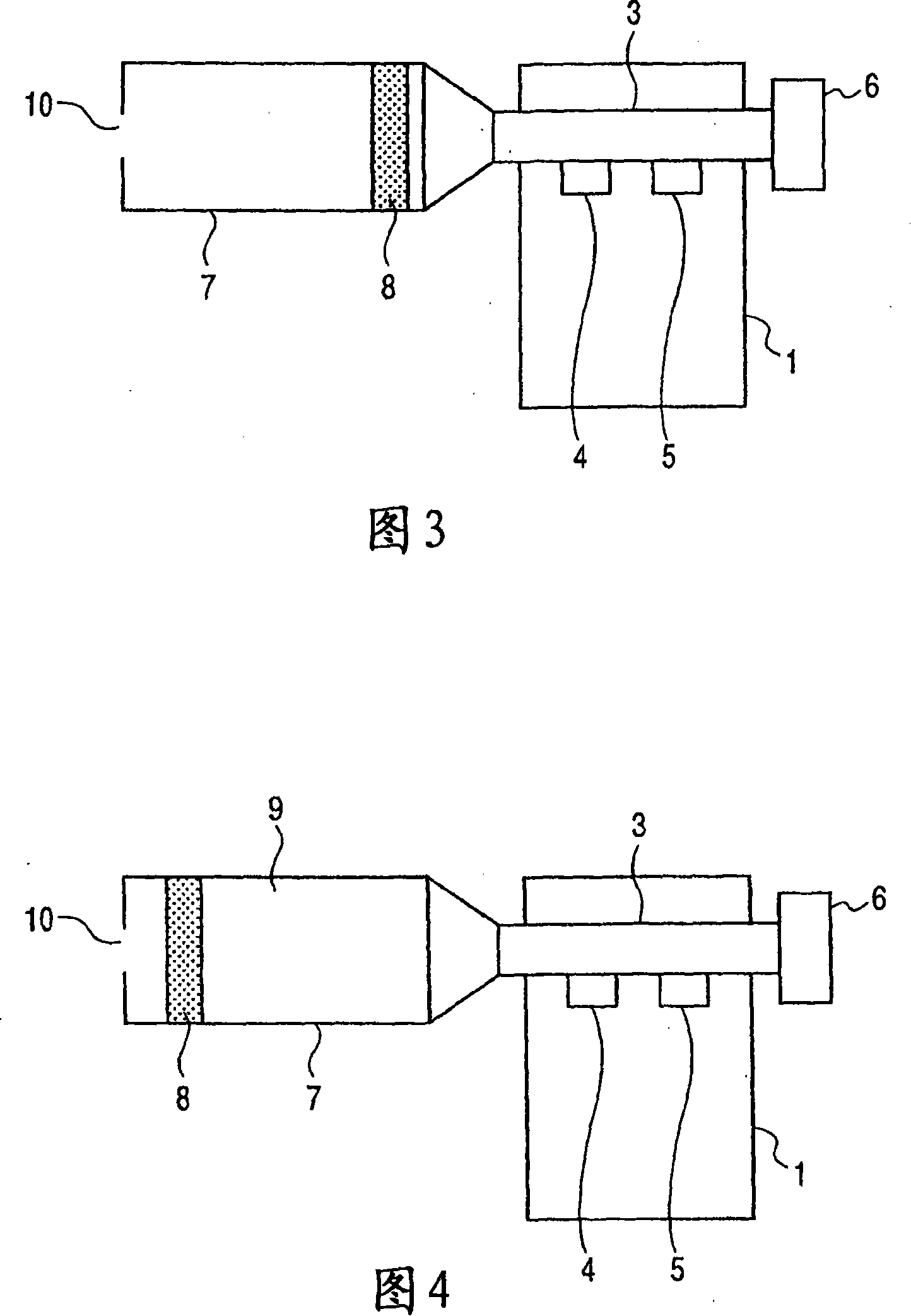
[0041] Figures 3 and 4 illustrate a second embodiment in which an air cylinder 7 is used as the gas storage means, replacing the container 2 in Example 1 (the container 2 collapses when the user inhales). In the state where the movable part 8 of the air cylinder 7 is on one side end of the flow path member 3 shown in FIG. Overflow through its openings (air holes), so that the movable part 8 moves through the interior of the cylinder 7, so that exhaled air is stored in the exhaled air storage part 9, resulting in the state shown in FIG. 4 . The exhaled air stored in the exhaled air storage part 9 has a substantially constant temperature and humidity of about 37° C. and about 95%, respectively, regardless of the surrounding temperature and humidity. Thereafter, the patient starts to inhale, so the gas kept at constant temperature and humidity that has been stored in the exhalation storage part 9 flows into the mouth of the patient, where the pressure sensor 5 detects the inhalat...
Embodiment approach 3
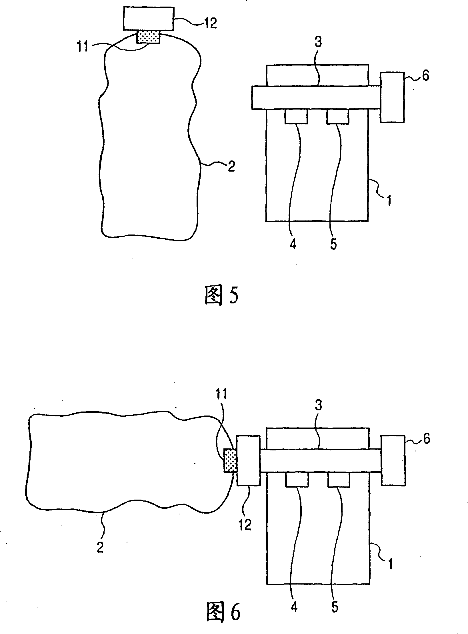
[0044] 5 and 6 are sectional views illustrating an inhalation device according to a third embodiment of the present invention. The container 2 in this embodiment is a container made of butyl rubber and has a volume of 500 ml. It has a closing mechanism 11 and an adapter 12 . Container 2 is a paper bag that crumples after the user inhales. The container 2 can be connected to and detached from the flow path member 3 through the adapter 12 . That is, the container 2 can be detachably connected to the flow path member 3 . In a state where the container 2 is separated from the flow path member 3 as shown in FIG. 5 , the gas is kept sealed in the air bag 2 in a constant temperature or constant humidity environment. The gas may be encapsulated by, for example, using a gas injector, a gas cartridge from which a constant temperature or humidity gas is stored, or may be encapsulated by the user's exhalation breath into it. The ambient conditions before which the gas enclosed in the ...
PUM
 Abstract
Description
Claims
Application Information
 - R&D
- Intellectual Property
- Life Sciences
- Materials
- Tech Scout
- Unparalleled Data Quality
- Higher Quality Content
- 60% Fewer Hallucinations
Browse by: Latest US Patents, China's latest patents, Technical Efficacy Thesaurus, Application Domain, Technology Topic, Popular Technical Reports.
© 2025 PatSnap. All rights reserved.Legal|Privacy policy|Modern Slavery Act Transparency Statement|Sitemap|About US| Contact US: help@patsnap.com


