Pipe cutting positioner

A technology of positioner and positioner, used in welding/cutting auxiliary equipment, auxiliary devices, plasma welding equipment, etc., can solve the problems of axial movement, slippage, inconvenient cutting, etc., and achieve the effect of ensuring stability

Active Publication Date: 2008-01-30
KUSN HUAHENG ENG TECH CENT
View PDF0 Cites 17 Cited by
  • Summary
  • Abstract
  • Description
  • Claims
  • Application Information

AI Technical Summary

Problems solved by technology

[0002] When plasma or electron beam is used to cut pipe fittings, especially large pipe fittings, positioners are usually used. The existing positioners usually use open gears for transmission, and an opening is opened on the transmission gear, so that the pipes to be cut The pipe fittings are set on the large gear through the opening, and the cutting is realized by rotating and displacing through gear transmission. However, due to the limitation of the manufacturing process, the nominal diameter of the large gear has an upper limit (maximum 1.5 meters), so when cutting large pipe fittings At the same time, the existing open gear transmission method is prone to slipping and axial movement during the working process. At the same time, it cannot meet the requirements of automatic cutting equipment and positioner synchronous linkage, which brings a lot of inconvenience to cutting.

Method used


Image

  • Pipe cutting positioner
  • Pipe cutting positioner
  • Pipe cutting positioner

Examples


Embodiment Construction

[0028] Embodiments of the present invention are described in detail below in conjunction with accompanying drawings:

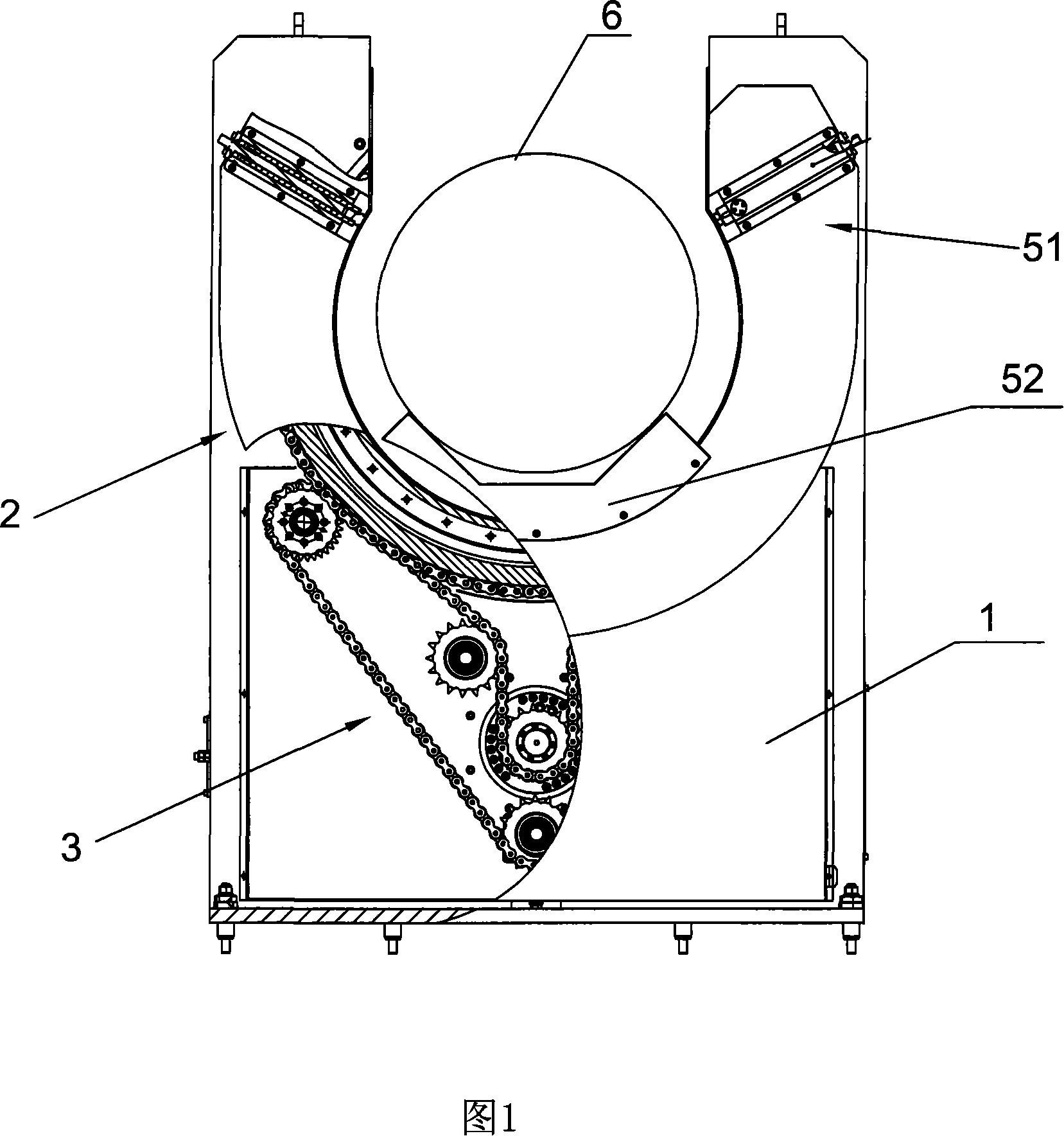
[0029] The positioner shown in Figure 1 includes a frame body 1, a rotation displacement mechanism 2 arranged on the frame body 1, and a rotation displacement mechanism 2 arranged on the frame body 1 to drive the rotation Displaced transmission mechanism 3.

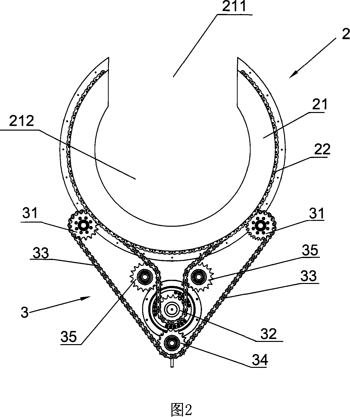
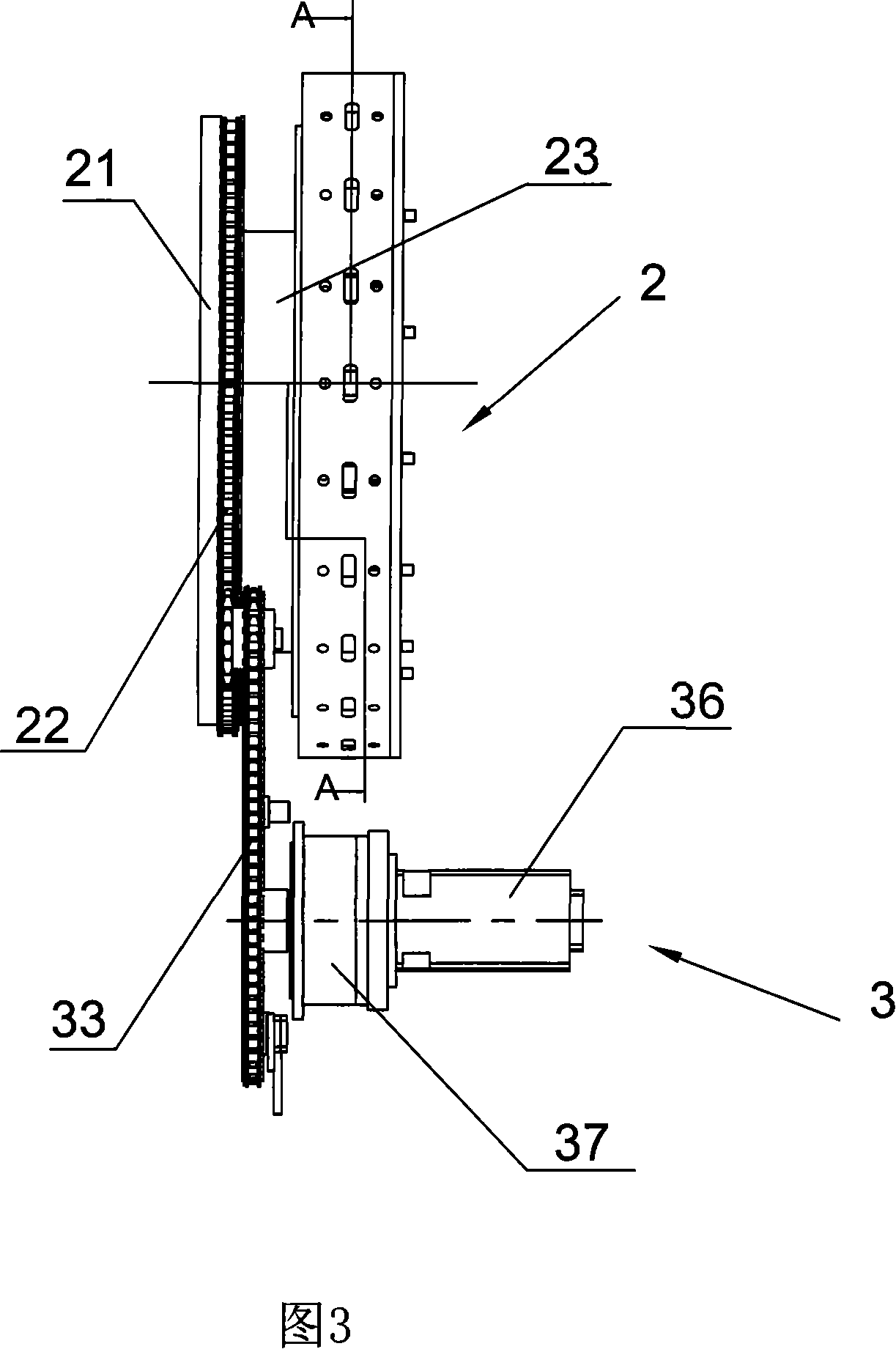
[0030] Wherein, as the rotary displacement mechanism 2 shown in accompanying drawing 2 to accompanying drawing 4, it comprises the rotating disk 21 that has hollow 212, and the diameter of rotating disk 21 can be made bigger, and corresponding hollow 212 also offers bigger, can like this Accommodates pipes of different diameters and sizes to be cut.

[0031] The turntable 21 is also radially provided with a gap 211 communicating with the hollow 212, through which the pipe to be cut 6 can be conveniently inserted into the hollow of the turntable, so this kind of positioner is also called It is an open po...


PUM


Abstract

The invention provides a cutting positioning machine which includes a frame body, a rotary positioning mechanism rotatablely arranged on the frame body, and a transmission mechanism driving the rotary positioning mechanism to rotatablely position; the rotary positioning mechanism includes a rotary disc with a chamber, a chain fixedly circled on the external circumference of the rotary disc, and a clamp positioning mechanism arranged at the chamber close to the rotary disc for clamping the pipes; the transmission mechanism includes at least one transmission chain wheel engaged with the chain; as the diameter of the rotary disc of the rotary positioning mechanism on the positioning machine is not restricted by the process, the large rotary disc can be added and meanwhile be matched with the clamp positioning mechanism, tightly clamping the pipes to be cut with different types, in particular to the large types; furthermore, the chain wheel is adopted for transmission, which ensures the stability of the rotation of the rotary disc, thus no skidding or axial movement occurring in the cutting process, and sequentially implementing the synchronous linkage between the cutting equipment and the positioning machine.

Description

technical field [0001] The invention relates to the field of metal pipe fitting cutting process equipment, in particular to a positioner for cutting large pipe fittings. Background technique [0002] When plasma or electron beam is used to cut pipe fittings, especially large pipe fittings, positioners are usually used. The existing positioners usually use open gears for transmission, and an opening is opened on the transmission gear, so that the pipes to be cut The pipe fittings are set on the large gear through the opening, and the cutting is realized by rotating and displacing through gear transmission. However, due to the limitation of the manufacturing process, the nominal diameter of the large gear has an upper limit (maximum 1.5 meters), so when cutting large pipe fittings At the same time, the existing open gear transmission method is prone to slipping and axial movement during the working process, and at the same time cannot meet the requirements of automatic cutting...

Claims


Application Information

Patent Timeline
Patent Type & Authority Applications(China)
IPC IPC(8): B23K37/047B23K37/053B23K15/08B23K10/00
Inventor 吴永平刘亚娟王书涛汪魁
Owner KUSN HUAHENG ENG TECH CENT
Why Eureka
Try Eureka