Ozone generator

An ozone generator and isolator technology, applied in ozone preparation and other directions, can solve problems such as components failing to work

Inactive Publication Date: 2008-01-30
刘辉堂
View PDF1 Cites 2 Cited by
  • Summary
  • Abstract
  • Description
  • Claims
  • Application Information

AI Technical Summary

Problems solved by technology

In the worst case, the co

Method used


Image

  • Ozone generator
  • Ozone generator
  • Ozone generator

Examples


Embodiment Construction

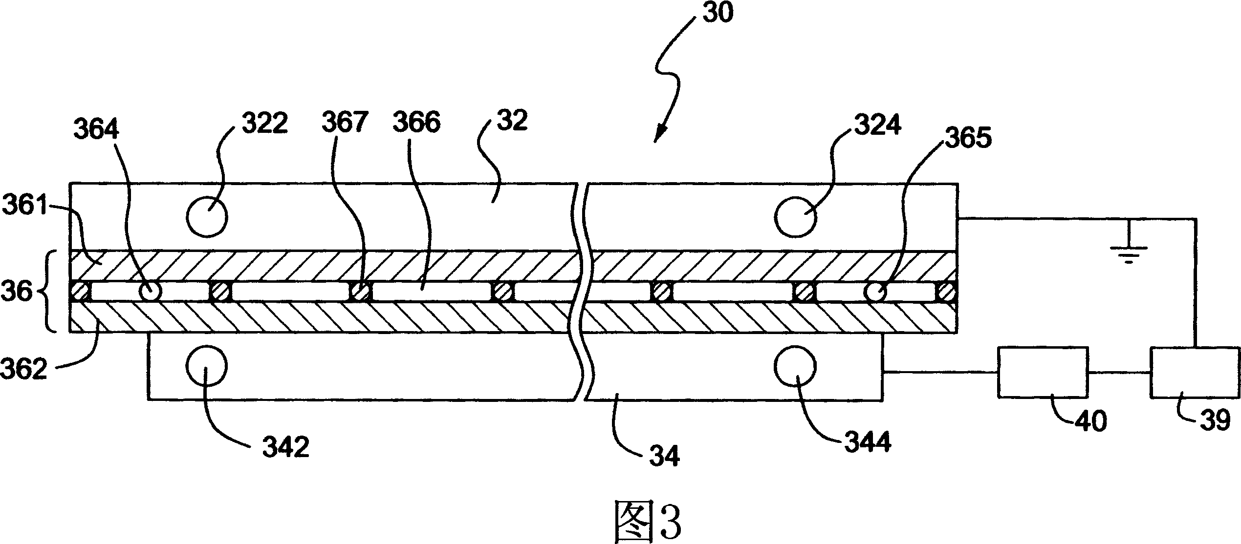
[0021] Fig. 3 illustrates a cross-sectional view of the structure of an ozone generator according to a first preferred embodiment of the present invention. As shown in FIG. 3 , the ozone generator 30 includes a cooling plate 32 , a high voltage plate 34 and a channel structure 36 . A cooling plate 32 is positioned opposite the high voltage plate 34 and a channel structure 36 is arranged between the two plates 32 and 34 . The high voltage plate 34 is further electrically connected to a power source 39 and a transformer 40, and the cooling plate 32 may be grounded. In addition, the cooling plate 32 may be a hollow plate including a hollow portion for filling coolant, and the openings 322 and 324 communicate with the hollow portion to allow the coolant to flow in and out. Similarly, the high voltage plate 34 may be a hollow plate that includes a hollow portion for filling with coolant, and openings 342 and 344 communicate with the hollow portion for coolant to flow in and out. ...


PUM


Abstract

The invention relates to an ozonizer which has the advantages of high production efficiency, small size, good heat dissipation and anti-aging capability. The ozonizer includes a cooling plate, a high-voltage plate arranged corresponding to the cooling plate, and a passage structure arranged between the cooling plate and the high-voltage plate. The passage structure includes a first plate which is provided with an internal surface and an external surface attached to the cooling plate, a second plate which is provided with an internal surface corresponding to the internal surface of the first plate and an external surface attached to the high-voltage plate, a plurality of side plates which connect the first plate to the second plate for conveniently defining the space between the first plate and the second plate, a first opening which is formed on the one side of the side plate for introducing the air into the space, and a second opening which is formed on the other side of the side plate for guiding the air out of the space. The structure of the ozonizer can be piled to form a piling module, and further forms an ozonizer piling component. The ozonizer piling component has the advantages of high ozone production speed, high volume flow speed and small dimension.

Description

technical field [0001] The present invention relates to an ozone generator, in particular to an ozone generator which is easily stackable and therefore of relatively small size. Background technique [0002] Ozone (O 3 ) is a gas that is widely used to remove pollutants from gases or liquids that need to be purified. Due to the unstable chemical properties of ozone itself at normal temperature and pressure, it is easy to combine with other pollutants to form benign compounds. Therefore, in recent years, ozone has been widely used as a cleaning gas, and has been used in home appliances such as washing machines, refrigerators, air conditioners, and various air cleaners. [0003] In a conventional method, an ozone tube is used to generate ozone. FIG. 1 illustrates the conventional structure of an ozone tube 10 . The ozone tube 10 comprises an outer ring tubular electrode 11 surrounding an inner ring tubular electrode 12 . Both the outer ring tubular electrode 11 and the in...

Claims


Application Information

Patent Timeline
IPC IPC(8): C01B13/11
Inventor 刘辉堂
Owner 刘辉堂
Why Eureka
Try Eureka