A tunnel kiln for ceramic products

A tunnel kiln and product technology, applied in the field of tunnel kiln, can solve problems such as temperature deviation

Inactive Publication Date: 2008-01-30
萨克米窑炉股份有限公司
View PDF0 Cites 10 Cited by
  • Summary
  • Abstract
  • Description
  • Claims
  • Application Information

AI Technical Summary

Problems solved by technology

[0014] Unfortunately, measurements from thermocouples located on the side walls are often affected by the presence of turbulence along said walls and the tight placement between the burners themselves
This means that the me...

Method used


Image

  • A tunnel kiln for ceramic products
  • A tunnel kiln for ceramic products
  • A tunnel kiln for ceramic products

Examples


Embodiment Construction

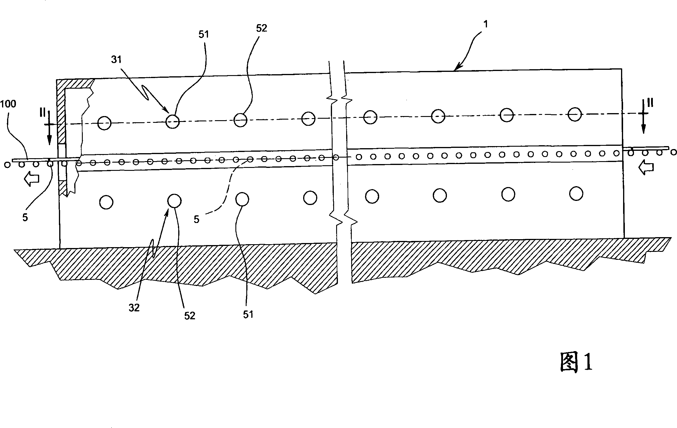
[0024] Referring to the above-mentioned accompanying drawings, among the figure 1 represents the whole of the tunnel kiln for ceramic products according to the present invention.

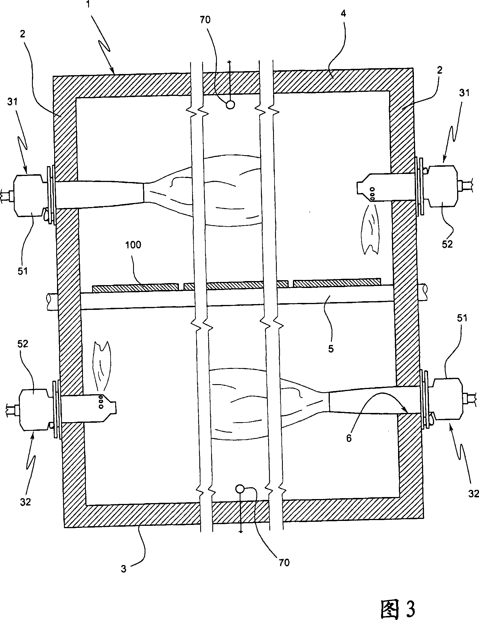
[0025] According to a very general description, the kiln 1 consists of two opposing side walls 2 , a kiln floor 3 and a kiln roof 4 .

[0026] A roller conveyor 5 of known type is provided inside the kiln 1 , which advances the ceramic product, in the embodiment described a ceramic tile 100 .

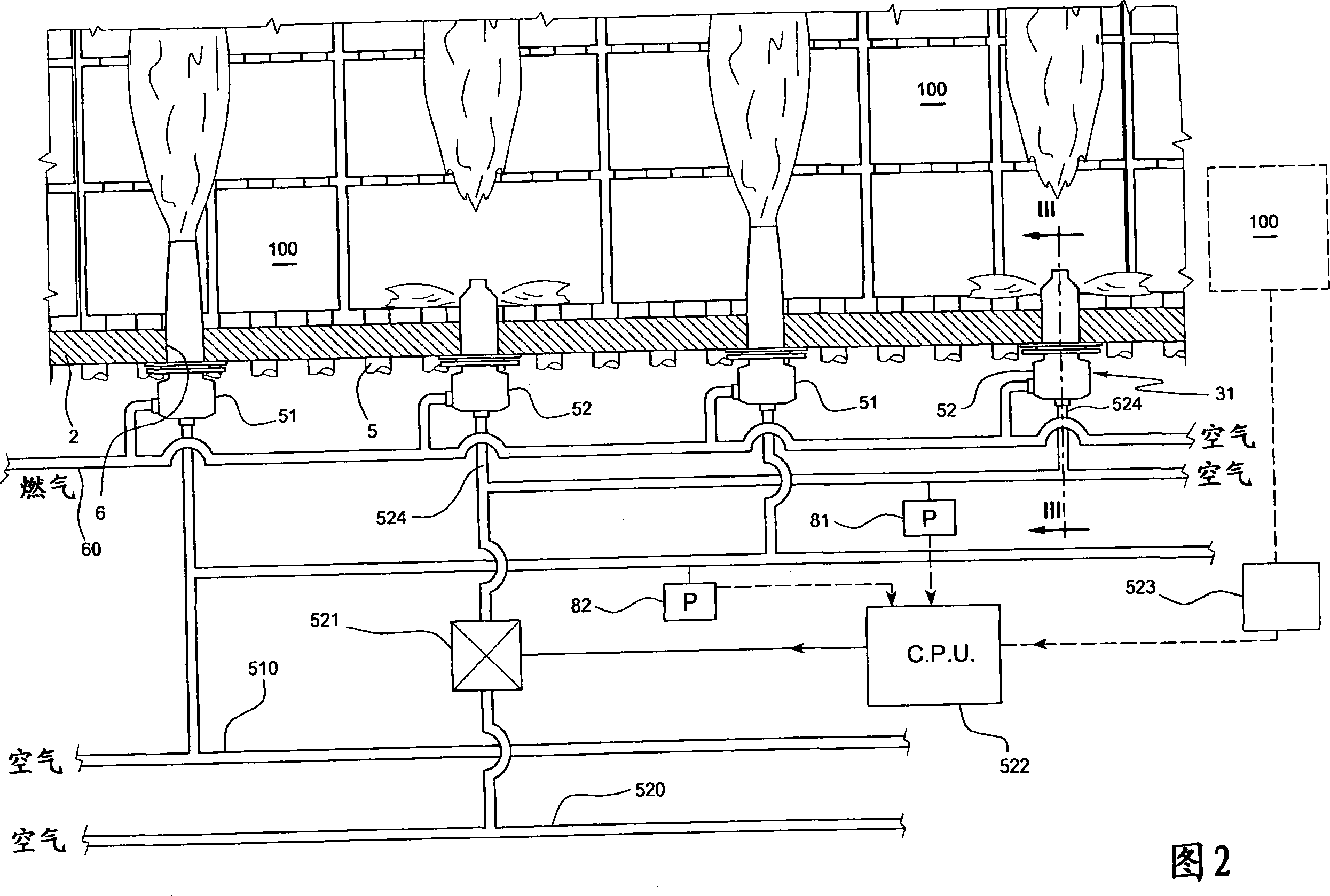
[0027] Two rows of gas burners 31 and 32 are arranged on each side wall 2 of the tunnel, respectively above and below the roller conveyor 5 .

[0028] Each row of burners is arranged inside a hole 6 formed in the side wall 2 of the kiln 1 .

[0029] Each row of burners consists of two different series of burners, 51 and 52 respectively, the burners of one series being alternately arranged with the burners of the other series.

[0030] Thus, there are four rows of burners 31, 32, two rows on one side wall an...


PUM


Abstract

A tunnel kiln (1) for ceramic products comprising two opposite lateral walls (2), a horizontal roller conveyor (5) destined to support and advance a layer of tiles (100) internally of the kiln (1), a first series of burners (51) and a second series of burners (52) arranged aligned along the two lateral walls and facing towards the opposite wall, each burner (51) of the first series (51) being provided exclusively with an axial flame such as to heat a central zone of the tunnel while each burner (52) of the second series is provided with at least a radial-flame nozzle such as to beat a zone which is proximal to the lateral wall of the tunnel, each burner (51, 52) of the first and the second series being connected to a common conduit (60) of combustible gas and respectively to a first (510) and a second (520) conduit of a comburent, comprising: means (523) for detecting a dimensional out-of-size with respect to a design project specification for the products exiting the kiln (1); a control unit (522) for receiving data coming from the means (523) for detecting; means for regulating (521) a flow rate of the comburent to the burners (52) of the second series on the second conduit (520) of the comburent, the means for regulating (521) of the comburent flow rate being controlled by the control unit (522) which is programmed to command the means for regulating (521) according to the data received from the means for detecting (523).

Description

technical field [0001] The invention relates to a tunnel kiln for ceramic products. [0002] In particular, the invention relates to tunnel kilns with roller conveyors on which ceramic products, such as ceramic tiles, are located. Background technique [0003] It is known to heat a tunnel kiln with two series of burners, one on each side of said tunnel, usually working with methane gas, the two series of burners being arranged on the side walls of the tunnel and towards the opposite tunnel wall. [0004] It is preferred to have two rows of burners on each side of the tunnel, one above and one below the roller conveyor. [0005] Groups of burners arranged in branches are supplied through separate gas pipes and to each group of burners via taps controlled by a temperature control system. [0006] The firing cycle of the tiles is determined very precisely by means of a firing map that provides for gradual heating of the tiles starting from the kiln inlet, holding the tiles a...

Claims


Application Information

Patent Timeline
IPC IPC(8): F27B9/20F27B9/36F27B9/40
CPCF27B9/40F27M2001/1517F27D21/02F27D19/00F27B9/36F23N1/002F23N3/002
Inventor G·皮费里
Owner 萨克米窑炉股份有限公司
Why Eureka
Try Eureka